
OSH Park
Profile for SmittyHalibut
Shared projects
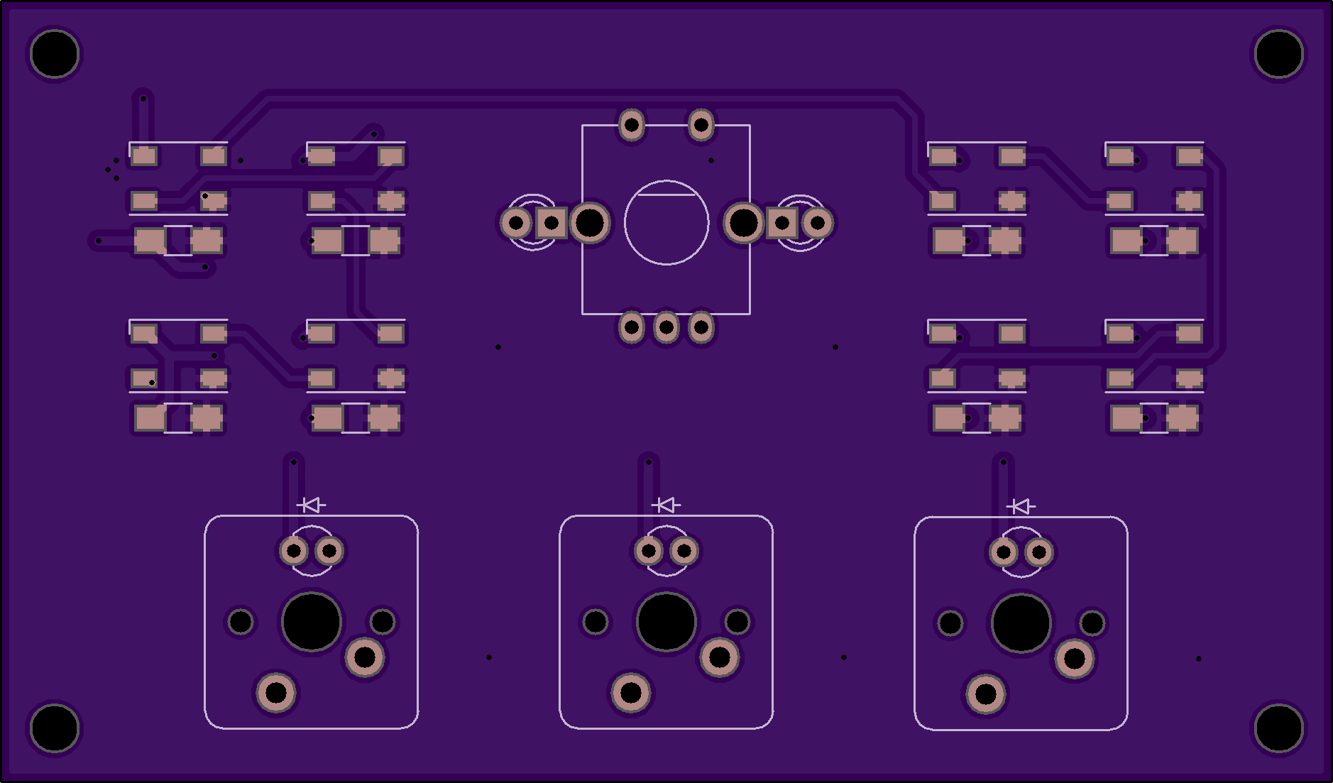
Halibut Transport v1.0a
by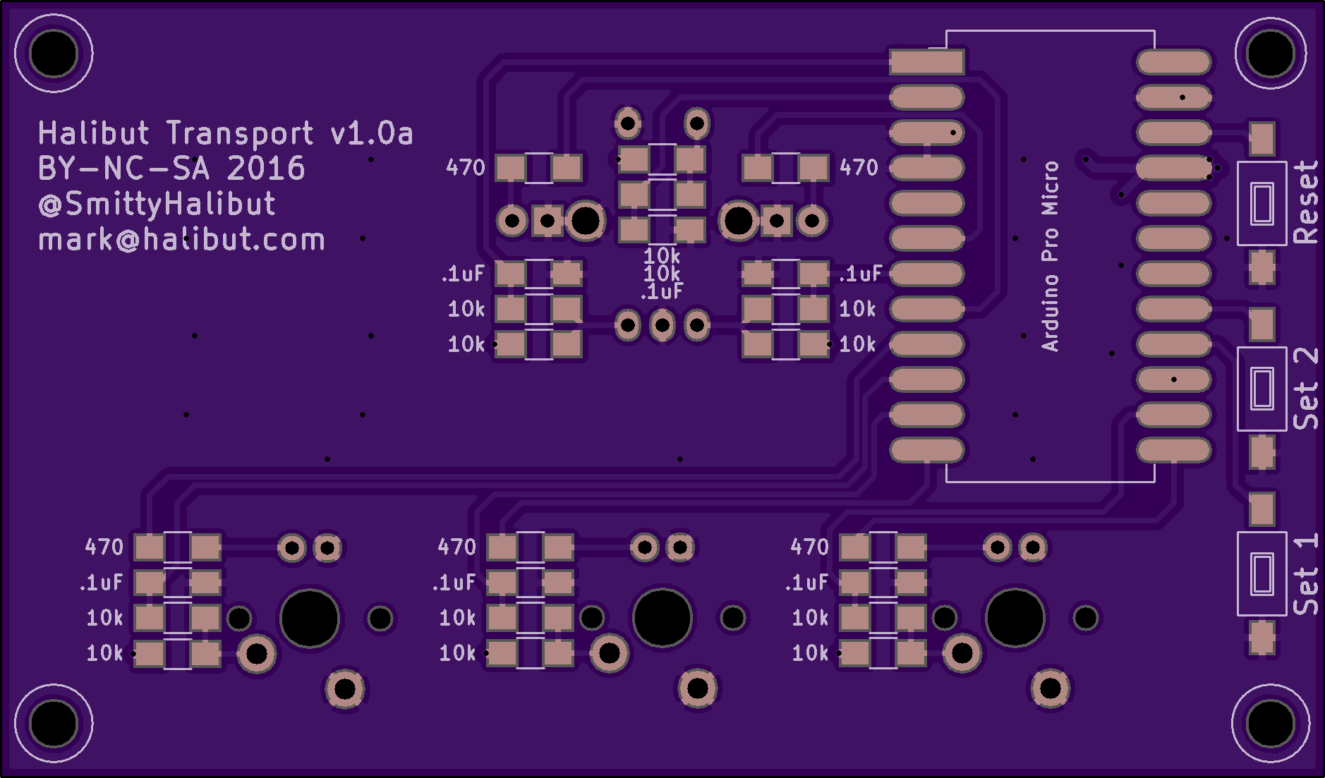
2
layer board of
3.76x2.21
inches
(95.40x56.03
mm).
Shared on
November 22nd, 2016 07:10.
A USB “keyboard” with just the Media keys. Really, you can program it for any keys you want, but I built it for the media keys my keyboard doesn’t have.
- Buttons are PCB mount Cherry MX switches, of your favorite color. I like Browns
- You’ll probably also want some key caps. This kit includes several options for media keys.
- The rotary encoder is also a pretty common part, but here’s an example.
- Microcontroller is an SparkFun Pro Micro
- The socket is a 24 pin “wide” socket, with the pins bent out so they can be soldered surface mount. It’s easier with the cheaper sockets rather than the really nice machined pin sockets.
- Buttons are pretty standard SMD 6x3x4.3mm buttons, for example.
- Passives are all standard 1206 bits, as marked on the board. Nothing is critical, 5% resistors and 10% caps are fine. Use your cheap crap here, not your good 1% components.
- I’m realizing I didn’t label the bypass caps next to the WS2812Bs. They’re all .1uF, like all the other caps on the board.
- The LEDs in the Cherries and immediately on either side of the rotary encoder are standard 3mm LEDs of your favorite color.
- The RGB LEDs on the “controls” side of the board are WS2812B (The Adafruit link provided are SK6812, but they’re compatible.)
- The board is sized to fit in my favorite cheap plastic project case. Having said that, I think I’m going to make a laser cut wooden panel to sandwich the PCB with stand-offs. I’ll post a link here when I’ve done something.
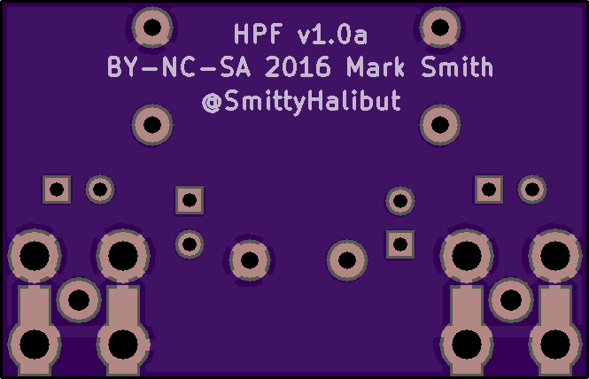
RF Highpass Filter
by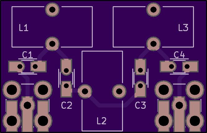
2
layer board of
1.33x0.86
inches
(33.81x21.74
mm).
Shared on
September 29th, 2016 07:05.
UPDATED 2016-12-21: Fixed filter calculator links. They now point to a) high pass instead of low pass, and b) T configuration instead of Pi. Sorry for the confustion.
A simple RF Highpass Filter. Component values are dependent on your filter requirements. I made this as an AM broadcast band blocker, cut-off at 1.7MHz. But you can put whatever values you want on it.
This board will work as either Butterworth filter (eg: http://www.calculatoredge.com/electronics/bw%20tee%20high%20pass.htm) or Chebyshev filter (eg: http://www.calculatoredge.com/electronics/ch%20tee%20high%20pass.htm). Put in your cut-off frequency, impedance is probably 50 ohms, and 7 components. (For Chebyshev, you’ll also need to specify the pass-band ripple tolerances.) Then click Calculate, and those are your component values.
This board will take either 1206 SMT capacitors, or .1" radial capacitors. It’s laid out assuming FT37-43 toroids for the inductors, but will probably work with axial pre-made inductors too, they just won’t lay flat on the board. The SMA connectors will take either vertical or edge mounted SMA connectors.
ESP8266 Clock Board
by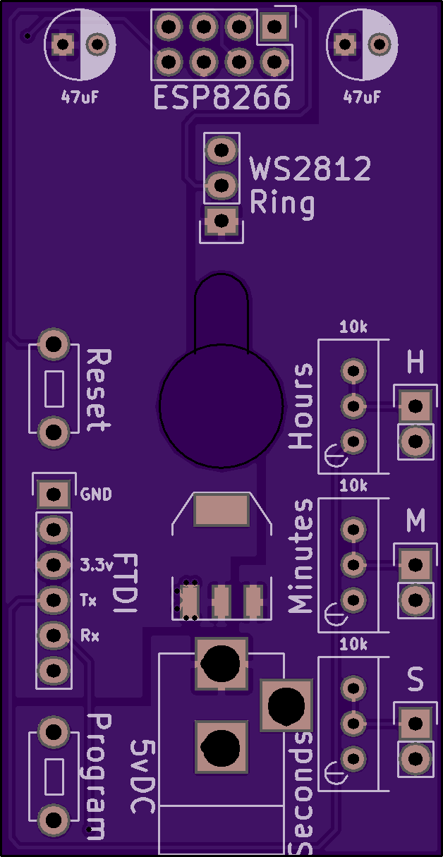
2
layer board of
1.26x2.43
inches
(31.90x61.75
mm).
Shared on
September 18th, 2016 20:41.
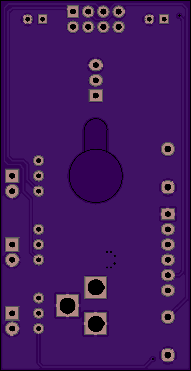
A controller board for a clock based on the ESP8266 uC. It will control a 60x WS2812 LED ring and turn it into a clock. There are also three analog outputs to make an Analog Panel Meter clock (the software isn’t written for this yet.)
This is an implementation of Jon Fuge’s wonderful Wol Clock project on Instructables: http://www.instructables.com/id/Wol-Clock-ESP8266-12E-60-LED-WS2812B-Analogue-Digi/?ALLSTEPS All software credit is his. I’ve modified it to use the -01 version of the ESP8266, and added the analog bits.
It uses the venerable (and cheap!) ESP8266-01 boards, about $2 from eBay: http://www.ebay.com/itm/171907296150
An example of the 60 WS2812 rings: www.ebay.com/itm/131594455055 There are several options available, they’ll all work.
All other parts are non-critical.
See https://www.youtube.com/watch?v=3o8EZLghdRY for the layout of this board.
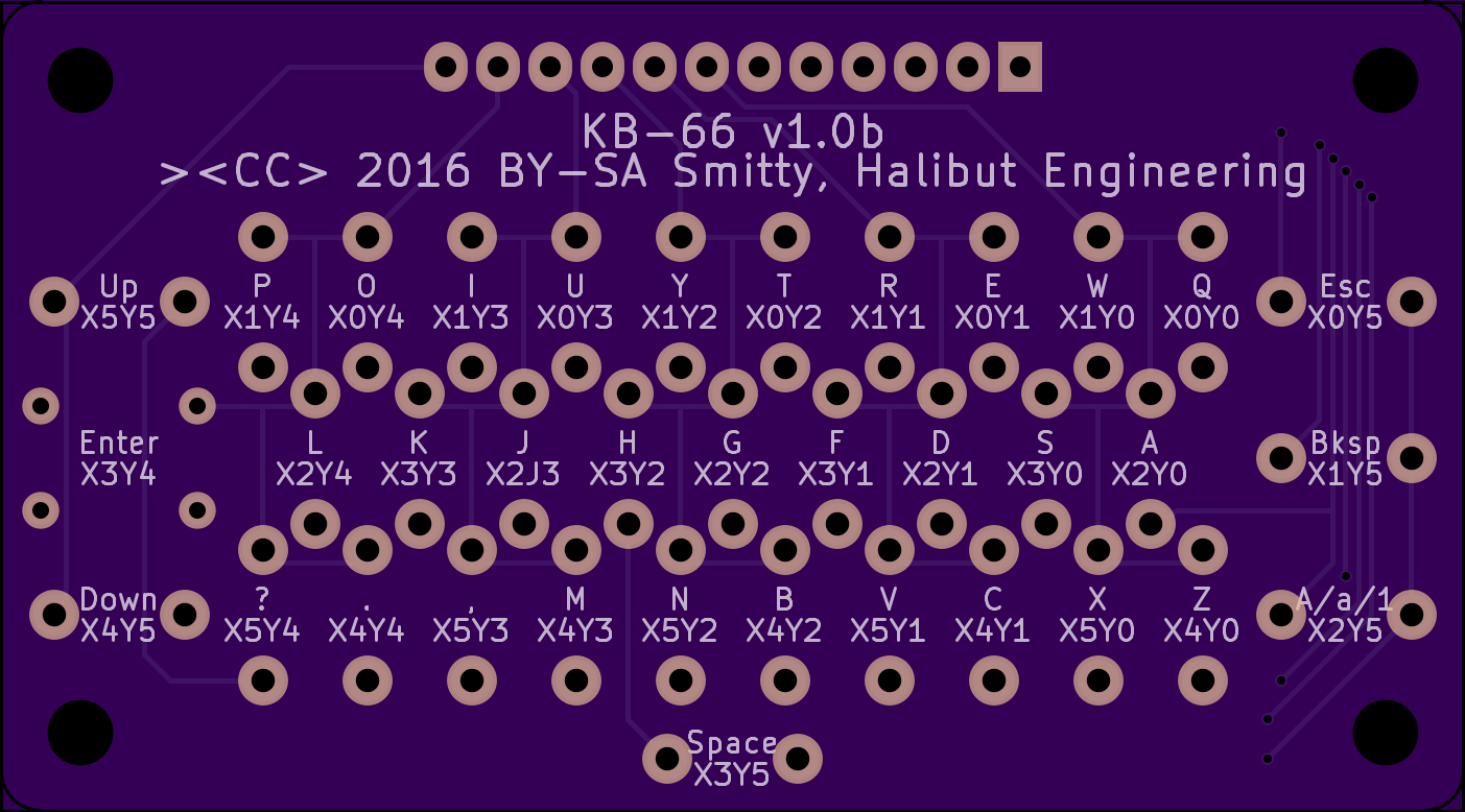
KB-66 v1.0b
by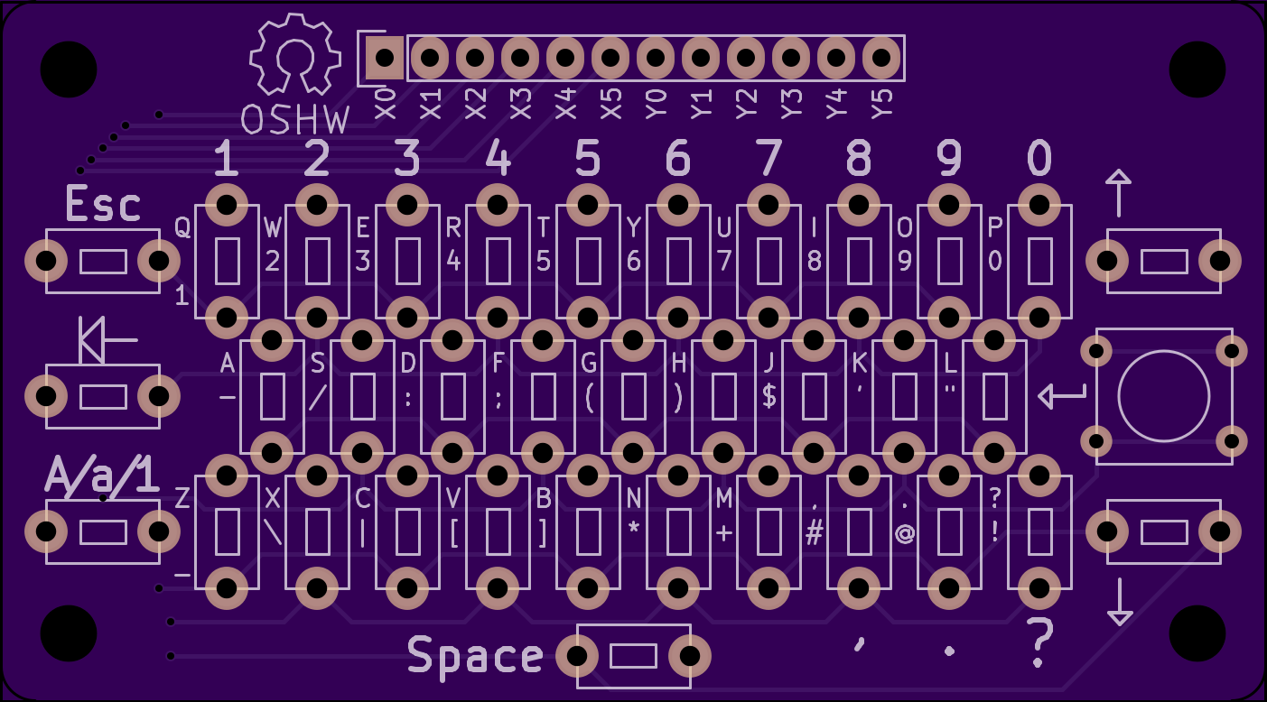
2
layer board of
2.81x1.56
inches
(71.27x39.52
mm).
Shared on
April 18th, 2016 03:38.
A 6x6 matrix Qwerty keyboard for microcontrollers.
Now with backspace!
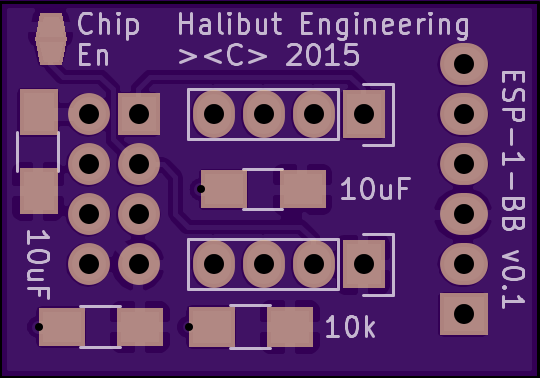
ESP-1-BB v0.1
by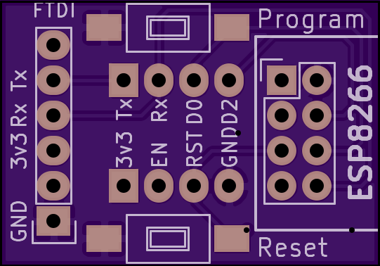
2
layer board of
1.08x0.76
inches
(27.46x19.20
mm).
Shared on
December 24th, 2015 01:33.
NOTE: The 30uF spec’d on the board is not sufficient to let an (read: my) FTDI serial cable (mine is actually PL2032) power the ESP8266. The ESP draws down the power line too much and the serial chip looses sync with my PC’s USB host controller. Either add more bypass caps (100uF or so?), or power it from an external 3.3v power source.
An ESP-1 ESP8266 breakout board. Includes:
- Pins spaced for breadboard use
- An FTDI serial header
- Reset and Program buttons
- Optional solder-blob chip enable
- 10k pull-up on Reset
- 3x 10uF power bypass caps (needs more than this if you intend to power it from your serial cable)
To put the ESP8266 into the programming state, push and hold the Program button, then push and release the Reset button, then release the Program button. The ESP8266 is now in Program mode and appears to stay there until you upload your program.