OSH Park
Shared projects
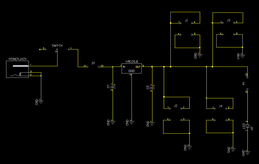
owlmv.zip
by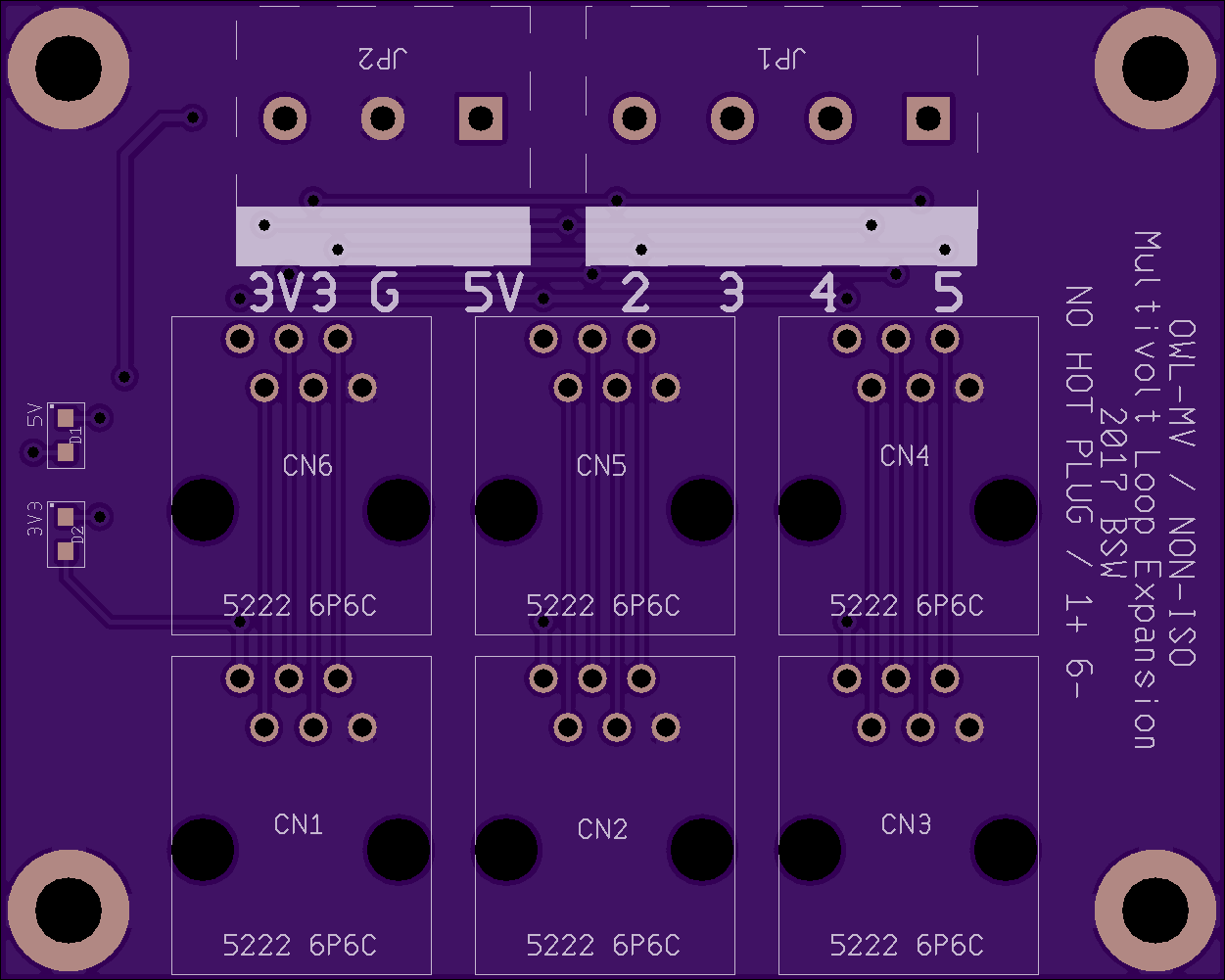
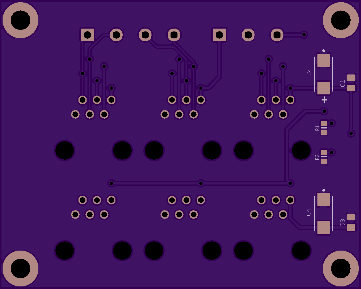
2
layer board of
2.50x2.00
inches
(63.53x50.83
mm).
Shared on
February 2nd, 2017 20:43.
A multivolt expansion board.
rsbb5volt.zip
by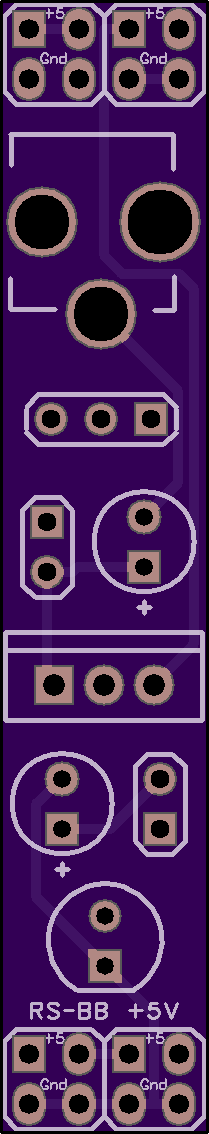
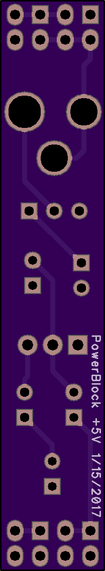
2
layer board of
0.42x2.27
inches
(10.64x57.63
mm).
Shared on
February 2nd, 2017 20:33.
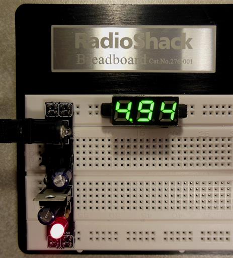
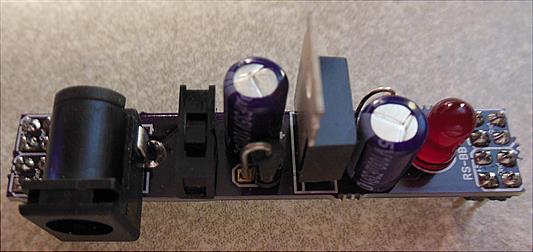
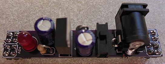
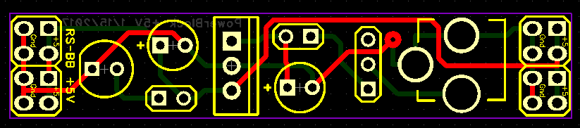
+5v Breadboard Power Supply for a RadioShack breadboard. This pcb was designed using DipTrace.
ltc3105_solar_cell_power.brd
by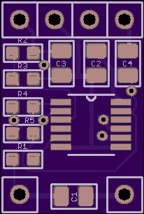
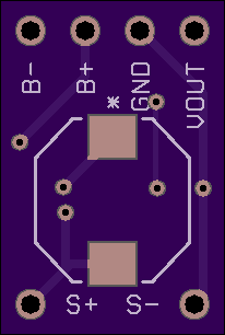
2
layer board of
0.41x0.61
inches
(10.44x15.52
mm).
Shared on
February 2nd, 2017 20:15.
Single Cell solar charger with 2 NiMH batteries that provides power for 1.8 device
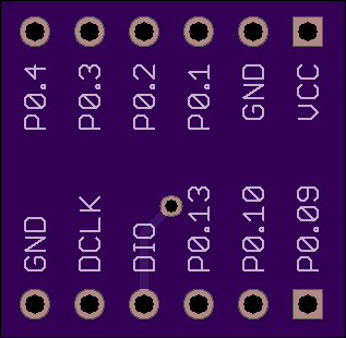
nRF51822-04AT breakout board v2
by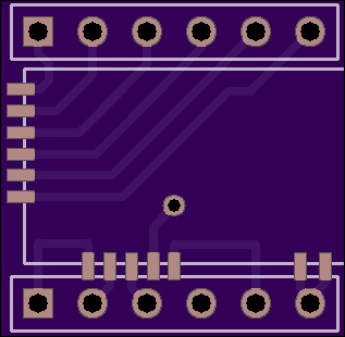
2
layer board of
0.63x0.62
inches
(16.08x15.75
mm).
Shared on
February 2nd, 2017 20:15.
Breakout board for nRF51822-04AT modules
The module is sold on eBay for about $3.59 with free shipping.
The module can be used as BLE Uart or reprogramed with $8 ST-Link/V2 programer using SWDIO and SWDCLK pins. nRF51 is well supported using free online mbed tools.
Changes from (v1 breakout board)
- Made the board spacing 500mil so it fits symbiotically on proto-board.
- The board is now smaller. There was too much space around the module that was not needed.
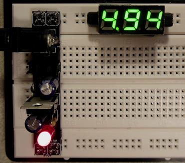
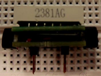
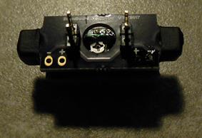
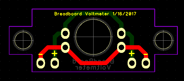
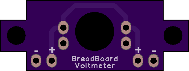
BBVM.zip
by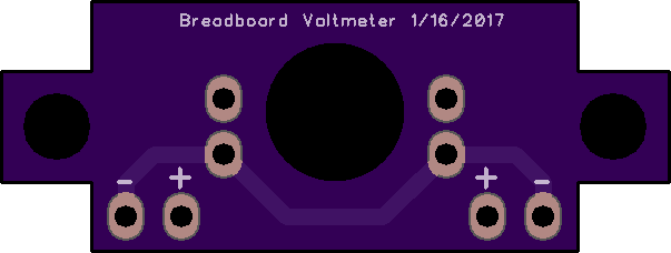
2
layer board of
1.21x0.46
inches
(30.66x11.58
mm).
Shared on
February 2nd, 2017 20:11.
This pcb was designed using DipTrace. This pcb was designed to be mounted to the Mini-In-The-Box Mini Voltmeter. The pcb connects to 4 male header pins that allow it to be plugged into a Breadboard power rail. The Voltmeter has two wires: Red wire for the positive voltage side and a Black wire for the negative voltage side. The Red wire is soldered to the + pad. The Black wire is soldered to the - pad. There is a pair of + and - pads on each side of the pcb but you only need to solder the Red and Black wires from the Voltmeter Module to one pair of + and - pads. The large circular hole in the center of the pcb allows you to access to the potentiometer on the back of the mini voltmeter so you can adjust it.