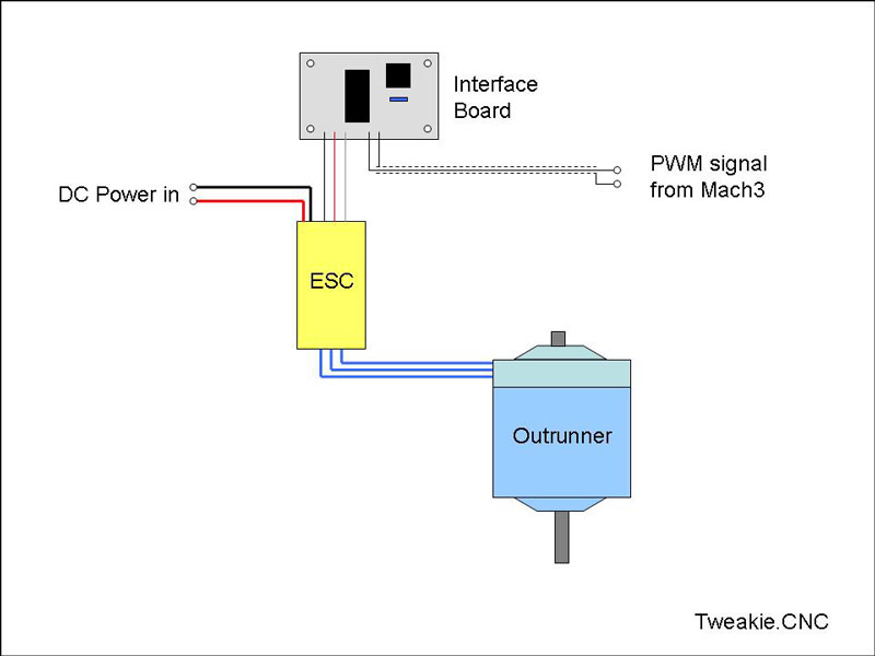
Their high speed and small size make Bldc motors ideal candidates for use as engraving spindles on most CNC machines and by providing software speed control they can also be used as general purpose spindles on small CNC machines.
This is not a new idea, it has all been done before and for those who would rather buy a ready-made unit then this controller from LogiCNC may be a good choice. http://www.logicnc.com/rcnc.html It may also be a good idea to study their instruction document to get an understanding of the principle etc.
For those, like me, who get pleasure from building their own things then please read on.
As far as the actual spindle construction is concerned then Robert’s 890kv-ox-rc spindle using an outrunner would certainly make a good choice as a build. http://openbuilds.com/builds/890kv-ox-rc-spindle.411/
Bldc motors use their own specialist drivers (ESC) which are controlled / operated by a pulse train in exactly the same way as an RC servo. The actual speed is controlled by a variable pulse width of between 1mS and 2 mS (with 1mS being off and 2mS being full speed) repeated at a pulse repetition frequency (PRF) of 50Hz.
By choosing a suitable Electronic Speed Controller which has BEC capability then this will also provide the necessary 5 Volt supply to power the Mach3 to ESC interface circuit I am describing in this build.
Although this build is typically Mach3 related there is no reason it cannot be adapted for use with any machine control software which provides a PWM spindle control output.
As an option (adding 2 extra components) the interface can also be operated manually, using a potentiometer to control the outrunner speed, if a PWM signal is not available.
My initial tests were carried out by controlling an RC servo from the Mach3 spindle PWM signal and this is a short video which demonstrates the principle.
For this test I have set a Mach3 spindle range of 0 to 100 to indicate percentage of motor speed so 0% is off and 100% is full speed (GCodes: S000 to S100). The GCodes M3 and M5 will turn the spindle on and off and the spindle will automatically be turned off if E-Stop is invoked.
At this stage I am just using a spare pcb (made for another project), the Microchip PIC12f683 and TTL gates for I/O buffering. There are no special requirements for the PIC and almost any of the 8 pin types could be used – I am just using the 12f683 because I have one to hand.
There is, of course, absolutely no reason why exactly the same principle of operation described here cannot be implemented with other R.I.S.C. devices such as the ATtiny, Arduino etc. it is just a matter of personal preference.

The actual interface circuit is very simple and this will be described in detail a bit further on, all the real work is being done in software by the microprocessor chip and this is the strategy I have used for it’s programming…
1) Check the input pin for a PWM signal.
2) If no signal is present then send a 1mS pulse to the output pin (this enables the GCode M3 / M5 to operate correctly and also stops the spindle in the event that E-Stop is activated).
3) If a signal is present then measure the duty cycle (pulse width). This is best done with 16 bit precision (mainly because we are measuring in uS and outputting in mS – a factor difference of 1000).
4) Scale the duty cycle’s pulse width (0 to 100%) - again working 16 bits into a proportionate 1 to 2mS output pulse (the actual, maximum, duty cycle pulse width in uS will depend on the Mach3 PWM base frequency chosen).
5) Send the output pulse to the output pin.
6) All this is then repeated forever within a timed 20mS loop.
The above works just fine for driving an RC servo but may need some modification, especially if the Mach3 spindle-on dwell time does not play nicely with the ESC’s start-up sequence – so, as always, I am learning as I go here.
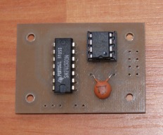
This is the interface board which has been isolation routed ( a quick, clean and easy method which is my preference for small and simple prototype pcb's like this) it has then been roller tinned before soldering the components. Whilst making I find it always pays to make a spare, just in case...
As mentioned earlier the circuit is extremely simple and basic. Obviously opto-couplers could have been used for the I /O buffering but my preference is just to use TTL gates. As each TTL gate inverts the signal, two gates are used in series to restore the logic state and using TTL in this manner creates a nice, clean, square wave for both the input to the PIC and subsequent output to the ESC.
I have now had a chance to test this out with two different ESC’s and Outrunner motors. They both behave differently with regard to minimum and maximum speed (the GCode Sxxx command) but both are capable of a wide range of speed settings in-between their min. and max.
For any wishing to construct this as a project you could, if you wish, use a ready made DB25 to DB25 jumper box enclosure (available from Amazon) to house the electronics. This is then inserted in series with the parallel port cable and the connection to the ESC brought out through the side.
http://www.amazon.com/DB25-Female-R...ref=lh_ni_t?ie=UTF8&psc=1&smid=A1SHTSJSJQA89P
Alternately you could make your own, using double sided PCB material, as I have done here – it is just a matter of choice.
The HEX file for programming the Microchip PIC12F683 is available from the Files tab above and the Mach3 settings are as follows;
Config. / Ports & Pins / Spindle Setup :-
Check, Use Spindle Motor Output
Check, PWM Control
PWM Base Frequency 500
Minimum PWM 0%
Config. / Ports & Pins / Motor Outputs / Spindle :-
Check Enabled
Set Step output pin# of your choice
Set Step Port (usually 1)
Config. / Spindle Pulleys :-
Min. Speed 0
Max. Speed 100 (this makes motor speed settings a %)
Tuning the interface circuit to a particular Outrunner motor…
As mentioned earlier the duty cycle width of the Mach3 PWM pulse is proportionate to the 500 Hz PWM Base Frequency that has been set. Small changes to this Base Frequency will allow the 1 mS through 2 mS output pulses to be lengthened or shortened slightly, acting in a similar manner to the Trim control on an RC transmitter.
Setting the Mach3 maximum and minimum pulley speeds, along with the minimum PWM is bit of a balancing act and requires max. and min. motor RPM measurement but it is possible to achieve, more or less, actual RPM settings for the GCode Sxxxxx command rather than % if this is preferred.
It should be remembered that supply voltage as well as shaft loading will affect the Outrunner’s speed quite considerably so, perhaps as another project I will look at a feedback system (measuring actual RPM) in an attempt to maintain constant RPM under varying load conditions – should be bit of a challenge.
This is the test rig that I have been using. The Outrunner is way too small to be used as a useful spindle but it has been just brilliant for testing and experimenting with different settings etc.
It has now been suggested that it would be nice to have a manual override switch so that the interface could also be operated with a potentiometer to control the outrunner speed independently of the PWM signal.
As the PIC 12f683 chip incorporates an A/D converter module this is an extremely simple task to accomplish and the updated circuit and layout diagrams are shown below. Both the switch and potentiometer could, of course be substituted with a rotary switch and fixed resistors giving an OFF and 3 or 4 pre-set speeds if required.
I have now re-written the software to allow for the option of Manual / PWM operation and have added a new downloadable HEX file (in the files section).

To be continued…
Software speed control of a brushless dc (Bldc) motor from Mach3.
Build in 'Other Builds' published by Tweakie, Jun 14, 2014.
Although this build is typically Mach3 related there is no reason it cannot be adapted for use with any machine control software which provides a PWM spindle control output. As an addition, an option has now been added which will enable the interface to manually control outrunner speed without the need for a PWM signal.
-
-
-
- Build Progress:
-
- Build in Progress...
Attached Files:
Derwin Palacpac, Colin Russon, Jestah and 6 others like this. -
-
Build Author Tweakie, Find all builds by Tweakie
-
- Loading...
-
Build Details
- Build License:
-
- CC - Attribution Share Alike - CC BY SA
-
Attached Files:
-
© XenZine Articles from Pick a Tutor


