Tool Position Setting Part III.
Using a WebCam.
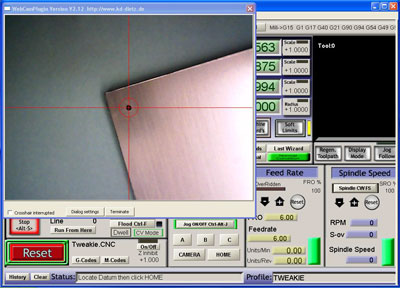
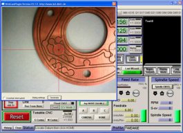
One of the many features of Mach3 is that an ‘on-screen video window’ can be used to display the image produced by a cheap USB2 webcam. This can be used for tool position setting in a similar manner and perhaps as an alternative to the laser cross-hair pointer described in Part I.

There is a choice of different video windows that can be employed and here I am using the Mach3 Camera plugin written by Klaus and freely available from his website http://www.kd-dietz.com/klausphp/index.html You may also like to download his Mach3 Screen designer for adding the screen buttons. Please note that the following is Mach3 related and all dimensions are in millimeters.
For operation of the webcam I have added 2 new VB buttons to my main Mach3 screen (CAMERA and HOME). Clicking the Camera button opens the video window, sets a slow jog rate and prompts for the datum to be located. Clicking the Home button closes the video window, resets the slow jog rate, moves the X and Y axis to centre the spindle / tool (over the datum previously located) and zero’s the X and Y axis DRO’s ready for the real work to begin.

This is the bracket made for mounting the webcam to my Z axis but after fitting I discovered that the guts of my camera are only secured at the cable exit end and any flexing of the cable can move the internal image sensor thus spoiling the positioning accuracy.

My solution was to remove (destroy) the front window, apply a couple of spots of adhesive (to secure the image sensor PCB to the housing) then make and fit a new window.

The VB (Cypress Enable) button scripts used are shown below but please be aware that they may not ‘copy and paste’ reliably because of the Unicode characters used (the usual problem relates to the ‘ character preceding the comments so this may need re-typing manually).
Please feel free to modify any of these scripts, as necessary, to suit your own particular application - they are really just a guide to get you started.
Camera button script;
Call SetUserLed(1102,1) 'open Klaus's video window
Call SetOemDRO(3,1) 'set slow jog rate to 1%
Code "(Locate Datum then click HOME)" 'message for status bar
Home button script;
SetUserLED(1103,1) 'close Klause’s video window
Call SetOemDRO(3,80) 'reset jog rate to 80%
Xs=GetOemDRO(59) 'read Xscale DRO
Ys=GetOemDRO(60) 'read Yscale DRO
Xmove = 70.850 * 1/Xs 'enter your camera offset here
Ymove = 1.070 * 1/Ys 'enter your camera offset here
Code "G91 G0 X" &Xmove & "Y" &Ymove 'make incremental move
While IsMoving () 'wait while that happens
Wend
Code "G90" 'go back to absolute moves
DoOEMButton (1008) 'zero X axis DRO
DoOEMButton (1009) 'zero Y axis DRO
Code "(Homing to Datum Complete)" 'message for status bar
Once it has been fitted, you will need to measure your camera offset (in my case it is 70.850 and 1.070) and enter the figures into the Home button script (The method for measuring the offset, along with other related details are similar to those described on the previous page for the laser cross-hair pointer setup).
Another interesting feature of Mach3 is the ease with which ‘Local System Rotated’ can be used for work positioning. Providing the work can be referenced from two points (a datum and a reference) and in this case two small holes along one edge then it does not have to be exactly or squarely placed on the work table in order to be accurately machined and this is a short video of the principle in action. http://www.graytel.talktalk.net/rotate1.wmv
The basic math’s (trigonometry) involved to achieve this is really quite simple -because the datum point is set X zero / Y zero then a movement to the reference gives the length of the Adjacent and Opposite sides of a right angled triangle.
The inverse of the Tangent then gives the angle of the work rotation thus; (b = Atn(X1pos/Y1pos)*(180/(4*Atn(1))).
Using the Screen Designer I have added 3 additional VB buttons (A, B, C) to my main Mach screen. Basically; clicking button A opens the video window and prompts for the Datum to be located - Button C zeros the X and Y axis and prompts for the Reference to be located - Button C closes the video window, does the calculation, moves the axis to the datum position, and sets Local System Rotate to the calculated value.
These are still under development and will, no doubt, be improved upon but here are the button scripts that I am currently experimenting with;
Button A script;
Call SetUserLed(1102,1) 'open Klaus's video window
Call SetOemDRO(118,0) 'reset system rotate DRO
Code "(Locate Datum then click Button B)" 'message for status bar
Call SetOemDRO(3,1) 'set slow jog rate to 1%
Button B script;
DoOEMButton (1008) 'zero X axis DRO
DoOEMButton (1009) 'zero Y axis DRO
Code "(Locate Reference then click Button C)" 'message for status bar
Button C script;
SubMain()
Call SetUserLed(1103,1) 'close Klaus's video window
X1pos = GetOemDRO(800) 'read x axis DRO
Y1pos = GetOemDRO(801) 'read y axis DRO
If (Y1pos=0) Then GoTo Label1 'avoid divide by zero error
b = Atn(X1pos/Y1pos)*(180/(4*Atn(1))) 'calculate angle
b = b - (b*2) 'change sign (+/-)
Code "G0 X0 Y0" 'move to datum
While IsMoving () ‘wait for task to be completed
Wend
Xmove = 70.850 'enter your camera offset here
Ymove = 1.070 'enter your camera offset here
Code "G91 G0 X" &Xmove & "Y" &Ymove 'make incremental move
While IsMoving () ‘wait while that happens
Wend
Code "G90" 'go back to absolute moves
Call SetOemDRO(118,b) 'set system rotate DRO
Label1:
DoOEMButton (1008) 'zero X axis DRO
DoOEMButton (1009) 'zero Y axis DRO
Call SetOemDRO(3,80) 'reset jog rate to 80%
Code "(Process complete)" 'message for status bar
End Sub
Again, the camera offset (distance between the camera centreline and the spindle / tool centreline) needs to be measured (as described previously) and the figures entered into the Button C script.
The system I have comprises; Mach3 version R3.043.066 running under WinXP sp2 and my PC supports USB2.
Other combinations may or may not work successfully so some experimentation may be necessary.
One further thought…
If, for example, a round circuit board was made and a datum and a reference had been established and the angle calculated (as mentioned above). This angle (angle1) could be stored as a VAR. If the round circuit board was removed from the work table then replaced (at a different angle) then by locating the same datum and reference and again calculating the angle (angle2) by subtracting one from the other the resultant angle when entered into the Local System Rotated DRO would be correct for work to be re-commenced on the circuit board as if it had never been removed and replaced.
It would perhaps be quite complicated to perform all the necessary math’s using a calculator but by using a VB script it could not be made more easy.
Tweakie.
Tool position setting Part III.
Build in 'CNC ROUTER BUILDS' published by Tweakie, Jan 29, 2014.
In this, the final part, I would like to introduce Machine Vision and show how it can be used, not only for tool position setting but also for resolving the triangle to calculate the G68 (local system rotated) for jobs which are not squarely placed on the work table.
-
-
-
- Build Progress:
-
- Build Complete!
3DMON, kram242 and Public Do Omens like this. -
-
Build Author Tweakie, Find all builds by Tweakie
-
- Loading...
-
Build Details
- Build License:
-
- CC - Attribution Share Alike - CC BY SA
© XenZine Articles from Pick a Tutor

