Welcome to OpenBuilds Community

Signup today and join in on the fun!

Sign Up

OpenBuilds OX CNC Machine

Discussion in 'CNC Mills/Routers' started by kram242, Dec 15, 2013.
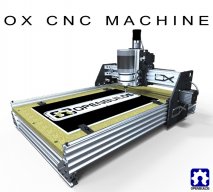
  1. Phillikl

    Phillikl Well-Known Builder

    Here is a general idea how big this sucker is. Was pre spoiler board and wasn't quite finished with the cabinet.

    Attached Files:

    Last edited: May 24, 2014
    kram242 likes this.
  2. oni305

    oni305 Veteran Builder

    Google : " windows xp sp3 standalone install "
  3. GrayUK

    GrayUK Veteran Builder

    GrandpawB: I can tell you how to get SP3 for XP Pro. You will need to contact me on: ggs@post.com
    Cheers
    Gray
  4. GrayUK

    GrayUK Veteran Builder

    Hi Phillikl: Looks good. Love the yellow infills. Pimp my CNC!! :D It looks huge. Is there definitely no flex in the X axis? Perhaps it's the camera angle that makes it look so wide and thin. But I'm going to build pretty much the same thing, so I will follow you into the CNC world at 1000mm wide.
    Cheers
    Gray
  5. JEFNLD

    JEFNLD New Builder

    Hello, im Jef and thinking about ordering/making an OX. I originally set my mind upon an Eshapeoko until i read about the OX. The V-slot design when the wheels are pushing on the sidefaces under loads, the wings of the V-slot profile are pushed and because of the profiledesign it has no flesh to push back, so they widen. Dont know how much but they do. Is it possible to add plates or just t nut thingies once every 100mm or so between the wings as in below picture?

    [​IMG]
  6. JustinTime

    JustinTime Veteran Builder

    True words and apply to most projects. LOL

    It can also cause you some hair loss since it may be a problem to get the axis to be a perfect 90 degree to the bed

    Excellent idea. Should have thought of it myself. :)

    I'll recommend using a permanent board for the construction of the machine and mount the spoiler board on it. That way, when it's time to change the spoiler board the machine stays as it is and only the spoiler board is removed.

    Is that your travelling speed or the cutting speed? I think 40ipm for cutting is the best speed but I may be wrong about this.
    Phillikl likes this.
  7. Phillikl

    Phillikl Well-Known Builder

    Sorry on mobile so it's a pain for the quotes.

    Z axis alignment: yes this can cause issues, but with some time and the patience of a saint you can get this accomplished. I was only having issues with 1 wheel so didn't have much problems with alignment. I'm currently only doing wood, until I get the $ for a spindle, a little off won't be an issue for 2.5D stuff. Once I get a spindle then I will have a bunch of questions! LOL

    X axis flex: I am not seeing any flex. This could be because I ran extra supports under the spoiler board on the outer edges. I also took extra time to cut the spoiler board to give a 1/16" gap between the X axis rails. Then once the board settled into place, used silicone to fill in the gap between the rails and spoiler board. Believe it or not the thing really stiffens up once that board goes in.

    Cutting speed: with planet cnc software it has programmed in soft stopping. I haven't messed with the default. For long runs (ie table leveling) was cutting around 200 ipm for the midsection without any issues. However with soft stop I am seeing around 20-30 ipm for smaller stuff and about 40-80 ipm for mid sized stuff (swag). I do not normally override (which will disable the soft stop feature) but when I do, I have it set to 150 ipm.

    I normally use cambam for a lot of drawings and have it set to 30 ipm, modifying this to 100 doesn't buy me any cut time, so i just leave it alone.

    Think I Covered everything. Have a happy and safe Memorial day!

    ~Kendall
  8. Phillikl

    Phillikl Well-Known Builder

    Hi Jeff.

    You have a great point, but think you may be over analyzing. Load distribution is across 3-4 top wheels and also inverse support by 2 bottom wheels. If I remember right these wheels are designed for 8 pounds of force. Being spread just shy of 7" should make the v slot immune to spread. I know we have a few mech engineers on here will definitely provide some better/more complete explanations for this, but for me personally haven't seen any issues. Before I would say you see rail separation I would bank on seeing belt and pulley jump or motor stall.
    JEFNLD likes this.
  9. GrayUK

    GrayUK Veteran Builder

    JEFNLD. Interesting. I can see how that might happen, and I can see how packing the unused slots with lengths of aluminium or steel could resolve the problem. However I've not heard from any of the more experienced Guys of it actually happening. Just how much stress are you putting on this V profile?
    Cheers
    Gray
  10. Phillikl

    Phillikl Well-Known Builder

    I actually got those to keep dust from getting in the slots, but really give the machine some pizazz! I added some work LED lights to the inside of the rails and tapped off my 12vdc power supple, really brightens things up!

    As far as X flex I am not seeing any while running. However I do get about 2.8 mm rack effect with the machine off. Running dual steppers on the X axis effectively reduce this to zero. However keep in mind that when you power up stepper motors they lock into the step they are closest too, so in theory they could be 2 steps off (3.6 degrees for me) so depending on pulley configuration that could be a problem. I put a couple marks that i know is true in the middle of the table and I have not seen any issues with this as of yet.

    Attached Files:

    Last edited: May 25, 2014
    Serge E. likes this.
  11. GrayUK

    GrayUK Veteran Builder

    Phillikl
    Bling! Bling! Bling!Bling! :cool: You could be setting a new trend here. Can you get anodizing dye in Pink! :oops:
    Yellow infills and LEDs, eat your heart out.

    Cheers
    Gray
    Phillikl likes this.
  12. JEFNLD

    JEFNLD New Builder

    Hi Phil :)
    Maybe i am :), thnx for your explanation. Maybe an mechanical engineer can tell us more :D
    Last edited: May 25, 2014
  13. JEFNLD

    JEFNLD New Builder

    Hi Gray :)

    I have absolutely no data about how much stress it will put on the profiles, i was just thinking about the construction and visualised the profiles made out of pasta and figured what could happen :D But i think it can not harm to stiffen up the unused slots with lenghts of aluminium/steel.

    I plan on milling hard wood/aluminium sheets with the OX if i decide to get one. I know the feedrates/cuthdepths will be small but i figure the amount of stress put on the profile is higher then when cutting softer stuff. The delrin wheels will be squeezed and in combination with the amount of lowering due too widening of the v-slot wings under load, i am curieus what that translates too on accuracy. Say i cut a groove 4mm deep over 500mm lenght will it be 3.7,3.8,3.95mm??
  14. Matt Byrd

    Matt Byrd New Builder

    I'm very very interested in building this in 2'x4' (and maybe eventually larger) but the part store is out of stock. Does anyone know when the parts will be back in stock?

    Great work so far and thanks for your work!
  15. GrayUK

    GrayUK Veteran Builder

    Come on guys I need some help here. I'm the new boy, what do I know. We need some advice here.
    Cheers
    Gray
  16. GrandpawB

    GrandpawB Journeyman Builder

    Thank you very much. I have SP3 , Sketchup and SketchUCam all loaded up and working fine. Runs extremely slow, but it works. :)
  17. Vunics

    Vunics New Builder

    Hi,

    This looks good, but I'm wondering if you can use to machine G-10 and FR-4? or is this strictly for wood and maybe aluminum?!
  18. Phillikl

    Phillikl Well-Known Builder

    From my understanding with proper speeds and bit selection these epoxy impregnated fiberglass materials are about as easy to mill as aluminum, you will definitely eat more bits though. However with that being said, your dust collection system needs to be top notch to handle the airborne contamination it will produce. Me personally (from the advice of a seasoned machinist) will not touch the stuff until I get a professional dust collection system and out of my garage.
    Last edited: May 26, 2014
    Robert Hummel likes this.
  19. Vunics

    Vunics New Builder

    Thanks, the the primary reason I want to build a CNC machine is to make jigs using G-10. So, I will definitely install some sort of dust collection on top. Can you tell me what the resolution and accuracy of this machine is?
  20. MechEng

    MechEng Well-Known Builder

  21. chip_breakin

    chip_breakin New Builder

    I'm sure it is pretty sturdy but with the introduction of those nylon spacers its going to flex quite a bit with some weight on it or when machining hard stock like aluminum or a hardwood.

    I have 3 1/2in thick HDPE mounts on my spindle now and it flexes wayyyy too much for comfort. Aluminum mounts are the way to go if you can do it.
  22. MechEng

    MechEng Well-Known Builder

    Yes the nylon spacers were more of a, "test and see" prototyping part than a functional part. If they prove to be too flexible, a person could easily swap them with something like cheap fender washers. I'm also looking for a low profile nut that might make it so the clamps can mount directly to the v-slot and get rid of the spacing washers all together.
  23. Phillikl

    Phillikl Well-Known Builder

    Resolution and accuracy are based on countless factors. I will try to give a quick breakdown.

    Resolution: software, controller board, stepper drivers and steppers all play into this. Remember with increased resolution you will loose torque. Technology brought us micro - stepping capabilities; while 256 micro steps sound pretty cool and may give you a better finished product, chances are it will not. Gecko produces one of the best stepper drivers made and they only go to 10 micro steps, there is a reason for that. These options are up to you and what you require.

    Accuracy: this machine has a potential to be extremely accurate. However there are many more factors to create a less accurate machine than accurate. Some things to take in consideration when determining your needs:

    Size: normally bigger means harder to make accurate.
    Workmanship: taking time to ensure cuts are square and accurate as possible.
    Spindle: while a router provides a great substitute for a VFD spindle, they will wear bushings much faster, thus creating inaccuracies. Also mounting for a spindles normally seem much tighter tolerances.

    As you can see, with all these factors involved it's almost impossible to say "how accurate this machine is"; However some maybe able to say how accurate their machine is.

    While this is a great starter build, there is a reason Thompson linear (and similar) rails are priced an arm and a leg. If you are looking for a hobby grade machine, this is a great start. If you are looking to mill aircraft parts, then you may want to look elsewhere and plan to spend 10X the $$.
  24. GrayUK

    GrayUK Veteran Builder

    Well that depressed me! :(
  25. Tweakie

    Tweakie OpenBuilds Team Staff Member Builder

    Don’t be depressed my friend, I think Phillikl has given a pretty accurate summary of the factors affecting accuracy and resolution – the final machine quality and it’s capability is very much in the hands of the builder.


    Tweakie.
  26. Serge E.

    Serge E. Journeyman Builder

    I finally have all the parts for my OX - somehow got M3 instead of M5 for some screws (saga continues). Then found a local Fastenal outlet just across street !! Actually on other side of the Whisky storage buildings in "backyard". It opened mere weeks ago, so not listed anywhere. Just have to buy larger quantity packs (100 or 50) so plenty of spares ...

    As mentionned earlier, I'll be pimping my OX as well. LED light rope ordered, thinking of trying Plasti-Dip for other parts of the OX, filling tracks as you did, dressing up wiring, ... Like you say, mechanics is only a few hours assembling. However, from there, it will take time to get things just as one would want and working properly.

    As I assembled the gantrys, found a few needed tweaks and tricks - pictures to follow :

    - if the Y axis steppers are mounted in the "high" position, regular head screws worked fine without rubbing on V-slot. Otherwise, need to add a shim to clear.

    - to assemble the front plate (Z-axis) to back plate (forming X-axis assembly), propping front plate sub assembly with long screws allows doing all 4 corners (sequence of spacer/eccentrics shim, wheel) a dream, place back plate on top, followed by nuts with a few twists. That is it. Tighten and you are done.

    - using regular head screws on front plate requires adding an extra shim to the wheel sequence of X-axis, shifting everything just enough to clear V-slot. I was forced to rob from other end of sequence as I was short 2 shims ... Might not be good for the wheel bearing now directly against last spacer/eccentric ??

    - to mount the Y and X axis NEMA 23, rather than tapping the steppers, use the screws saved from the wheel kits and bolt steppers from back. These screws are otherwise shelved for an other project. Yes, a bit long, but the stepper casing is longer still, so no one will notice. My steppers did not allow for tapping - larger holes than required for tapping !

    - same "recycling" can be done with mounting the wheels for Z-axis. The extra thread sticking out should come in handy for mounting ... Something. I didn't reach that point yet ;) Or, it will be in the way ... ;(

    - somehow, I need to get 2 M5 x 20 mm to mount the ACME block on Z plate... Using the 15 mm (actually have 16 mm) is way too short and anything more than 25mm will rub the V-slot.

    Now I have to cut the 1500 mm 20x80 in half, cut a piece of 20x60 for the Z, do loads of tapping at their ends (not looking forward to this part) and mechanical assembly will be "done".

    A few good points made by others from your mounting the table beneath for added Z travel will make me think again on taking that approach. But the table must add strength as well as being "true".

    Going with a 750 (Y) x 1500 (x) going for an "infinite" length x 4' wide work area with an eventual "open" bottom area to add extra depth (as when working on the body mold for scale monster truck needing total of 6+") and having a 4th axis (ie turn the body mold at least a 1/4 turn to "clear "head/tool assembly over mold - manual keyed rotation at first). In fact, for front and back body work, the piece would need to be mounted vertically mostly beneath the table as it can be 20+" long).

    I might find out that an all in one machine is not better than a few "specialised" machines. But the garage is only so bib, as is the budget ...

    I will be on the road this coming weekend (niece's college grad), so i'll disappear again for a few days. Following weekend should have my OX fully assembled ;)) Then comes the fun part : making it work !
  27. Serge E.

    Serge E. Journeyman Builder

    There are kits for anodizing "at home". Mark has one listed in the ressources here. But it is not cheap (was it 500+$ just to get started ?). It involves acid (!) and other chemicals. The process, even for small parts, is not one you would want to do just once in a while for one or two parts. Otherwise you waste (get vapours!) ...

    Maybe try the spray on chrome finish instead ? Might not be as durable, but can respray as needed just about any time ... Could do some fancy colour effects with paint on approach. Of courae, it does not add anything to base material property.
  28. brjig

    brjig Well-Known Builder

    The 8mm threaded rod in the store is 1000mm in length.
    Does that need to get cut down in length for this project? 1000mm is 3feet. I doubt that the Z-axis of travel is 3 feet.

    Thanks
  29. dddman

    dddman Journeyman Builder

    @brjig

    Yes you have to cut it down and you'll have plenty left for other projects!
  30. bobt

    bobt Journeyman Builder

    But then again having a 1000mm Z axis has to help somewhere.

    Bob
    Phillikl and Duane like this.

Share This Page