
OSH Park
Profile for Eric
Shared projects
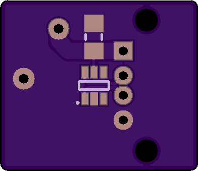
14V/28V to 5.1V 2.5A USB Power Supply
by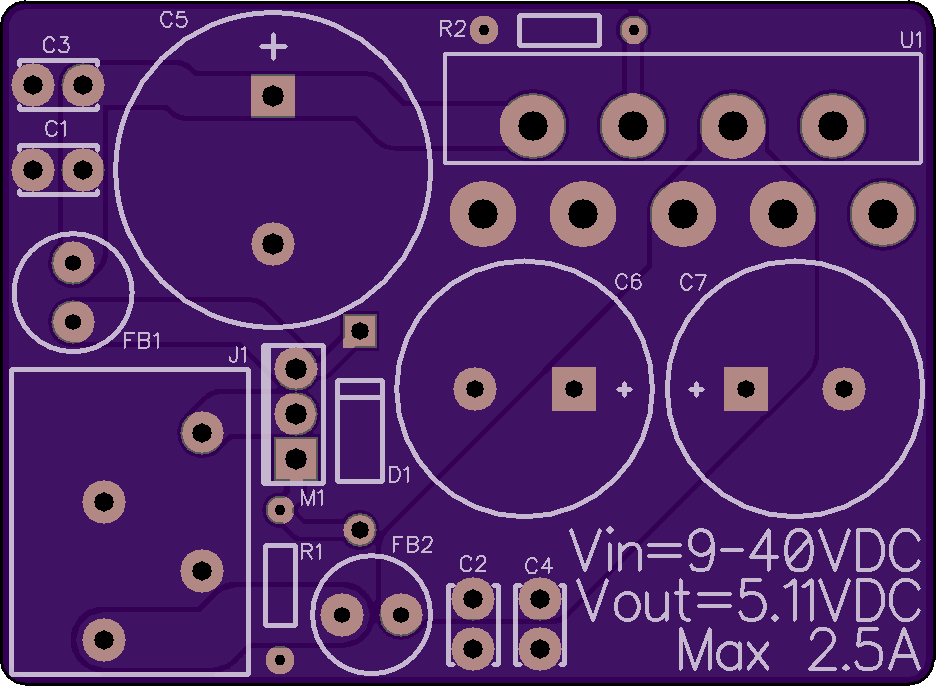
2
layer board of
1.87x1.37
inches
(47.52x34.82
mm).
Shared on
May 27th, 2017 23:14.
Cost: $12.80 for three boards.
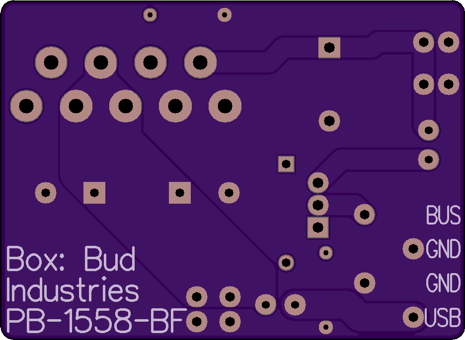
CORRECTION: If you built my earlier share of this PCB and got 0.5V output, it can be fixed by lifting the right-hand leg of R2 out of its hole and wiring it to ground at pin 3 of the MPM01 module (the PCB incorrectly routed R2 to Vout). This version is corrected and works without modification.
Description: 14V/28V to 5.1V DC/DC power supply for use as a USB charger in Experimental category aircraft. For use with my Single USB Charging Adapter board.
This board includes filter components (C1-C4, FB1-FB2) to eliminate switching noise at ADS-B/transponder and VHF communications frequencies. D1, M1 and R1 provide reverse polarity protection.
For anyone who wants to use this board in situations that don’t require noise filtering at 127MHz and 1.09GHz, you can eliminate FB1, FB2 and C1-C4. Instead, install wire links from the top pin of M1 to the top pin of FB1 (with board oriented as in the image above), and across the pins of FB2. If you don’t need reverse polarity protection, eliminate D1, M1 and R1 as well, and install the first wire link from the center pin of M1 to the top pin of FB1.
Alternative output voltages can be obtained by changing the value of R2. See the Sanken MPM01 datasheet and application note for details.
Bill of Materials: Click here for a Digi-Key shopping cart containing all necessary components.
- C1, C2: TDK Corporation FG18C0G1H4R7CNT06 4.7pF 50V ceramic capacitor
- C3, C4: TDK Corporation FG18C0G1H331JNT06 330pF 50V ceramic capacitor
- C5: KEMET ESW108M050AM7AA 1,000uF 20% 50V aluminum electrolytic capacitor
- C6, C7: KEMET ESY108M035AL4AA 1,000uF 20% 35V aluminum electrolytic capacitor
- D1: Fairchild/ON Semiconductor 1N5247B 17V 5% 500mW Zener diode
- FB1, FB2: Laird-Signal Integrity Products 28C0236-0EW-10 998-ohm @ 100MHz 5A ferrite bead
- J1: Phoenix Contact 1985218 3.5mm-pitch 4-position wire-to-board spring terminal block
- M1: Infineon Technologies IRFU530PBF 55V 31A P-channel MOSFET
- R1: Stackpole Electronics RNMF14FTC10K0 10k-ohm 1/4W 1% resistor
- R2: Stackpole Electronics RNMF14FTD499R 499-ohm 1/4W 1% resistor
- U1: Sanken Semiconductor MPM01 DC-to-DC converter module, 9-40Vin, 1.8-12Vout, 3A
- Box: Bud Industries PB-1558-BF black ABS flanged potting box, 2"L x 1.5"W
Note: Do not substitute alternate parts for C1-C4 or FB1-FB2. These components were selected for their specific frequency/impedance characteristics. Other parts, even of the same value, may not provide the same noise filtering at the desired frequencies.
Download: Click here to download a .PDF schematic of this board.
Electrolytic Capacitor ESR Tester
by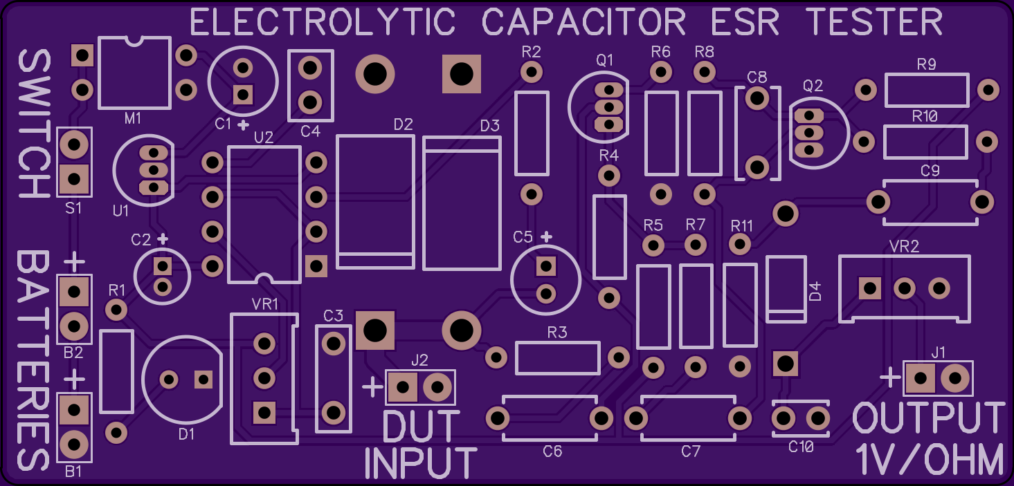

2
layer board of
2.93x1.41
inches
(74.45x35.71
mm).
Shared on
May 10th, 2017 03:43.
Cost: $20.60 for three.
Description: This board tests the equivalent series resistance (ESR) of electrolytic capacitors and outputs 1 volt per ohm to a multimeter. The design is tested and working.
BOM cost is ~$13 for just the components to populate the board. Click for a Digi-Key shopping cart with those parts.
For cheaper trimmer potentiometers, click to search eBay for “3296W 1M” and “3296W 5k”, sorted by price.
Notes:
R1 and D1 are optional power-on indication; the board will work without them.
M1 is not obviously marked for pin 1 location. Place part with its conjoined legs on the left, with the board oriented as shown in the OSHPark rendering above.
Download: Click here for a .ZIP archive containing the schematic, DipTrace v3.0.0.1 CAD files and RS-274X Gerber files.
Single USB Charging Adapter
by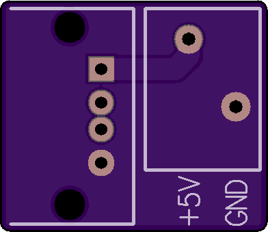
2
layer board of
0.78x0.68
inches
(19.89x17.17
mm).
Shared on
May 10th, 2017 01:28.
Cost: $2.60 for three boards.
Description: Adapts a 5V supply into a single-port universal USB charger. For use with my 14V/28V to 5.1V 2.5A USB Power Supply board.
Bill of Materials: Click here for a Digi-Key shopping cart containing all necessary components.
- Texas Instruments TPS2514A 1-port Dedicated Charging Port controller (SOT-23-6)
- Samsung CL31B104KBCNNNC 0.1uF 50V X7R ceramic capacitor (1206)
- Phoenix Contact 1985195 2.5mm-pitch 2-position wire-to-board spring terminal block
- Amphenol MUSB-A111-30 rugged USB panel-mount connector
Download: Click here to download a .PDF schematic of this board.
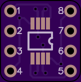
8-SOIC & 8-MSOP Breakout Board v2
by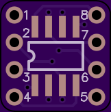
2
layer board of
0.41x0.41
inches
(10.34x10.44
mm).
Shared on
April 27th, 2015 23:54.
Cost: $0.80 for three.
Breakout board for 8-SOIC and 8-MSOP packages. Converts these 8-pin SMD components to breadboard-friendly 0.1-inch pitch by 0.3-inch width through-hole format. Pins numbered on both sides for quick reference.
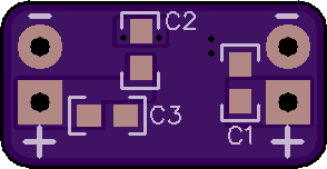
2.7-4.9V To 5V 250mA Mini Boost Converter
by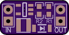
2
layer board of
0.59x0.30
inches
(14.96x7.70
mm).
Shared on
March 11th, 2014 02:39.
Cost: $0.85 for three.
Description:
Miniature DC-DC boost converter for powering a microcontroller or sensor from battery power. This board will operate from 2.7-4.9V, so you can use two or three AA cells, one lithium cell such as a CR123A, 14520 or 18650, or one lithium-ion rechargeable.
With the feedback resistors specified, output is 5V, and the board can supply about 250mA. At 250mA load the components get warm, but temperatures are well within limits.
Bill of Materials:
- U1: Texas Instruments LMR62014XMF Boost Regulator (SOT-23-5)
- L1: Bourns SRN3015-100M 10µH Shielded Inductor (SMD 3mm x 3mm) NOTE: If this part is out of stock, virtually any other 10µH, 3mm x 3mm SMD inductor will work fine.
- D1: ON Semiconductor MBR0520LT1G 20V 0.5A Schottky Diode (SOD-123)
- C1, C3: Yageo CC0603KRX5R6BB475 4.7µF 10V 10% X7R Ceramic Capacitor (0603)
- C2: Samsung CL10B681KB8NNNC 680pF 50V 10% X7R Ceramic Capacitor (0603)
- R1: Stackpole RMCF0603FT10K2 10.2kΩ 1/10W 1% Resistor (0603)
- R2: Stackpole RMCF0603FT3K32 3.32kΩ 1/10W 1% Resistor (0603)
BoM Cost: $2.97
Notes:
Output voltage is set by resistors R1/R2. See the LMR62014XMF datasheet for details on setting other output voltages. Keep in mind that a large change will also require changes in inductor and capacitor values. You can safely change to 3.3V output from two AAs or a lithium cell by changing R1 to 1.69kΩ, R2 to 1kΩ and C2 to 1500pF.
Output pads are 0.1-inch pitch and will accept standard pin headers. They are spaced 0.445 inch apart.