OSH Park
Profile for PaulStoffregen
Shared projects
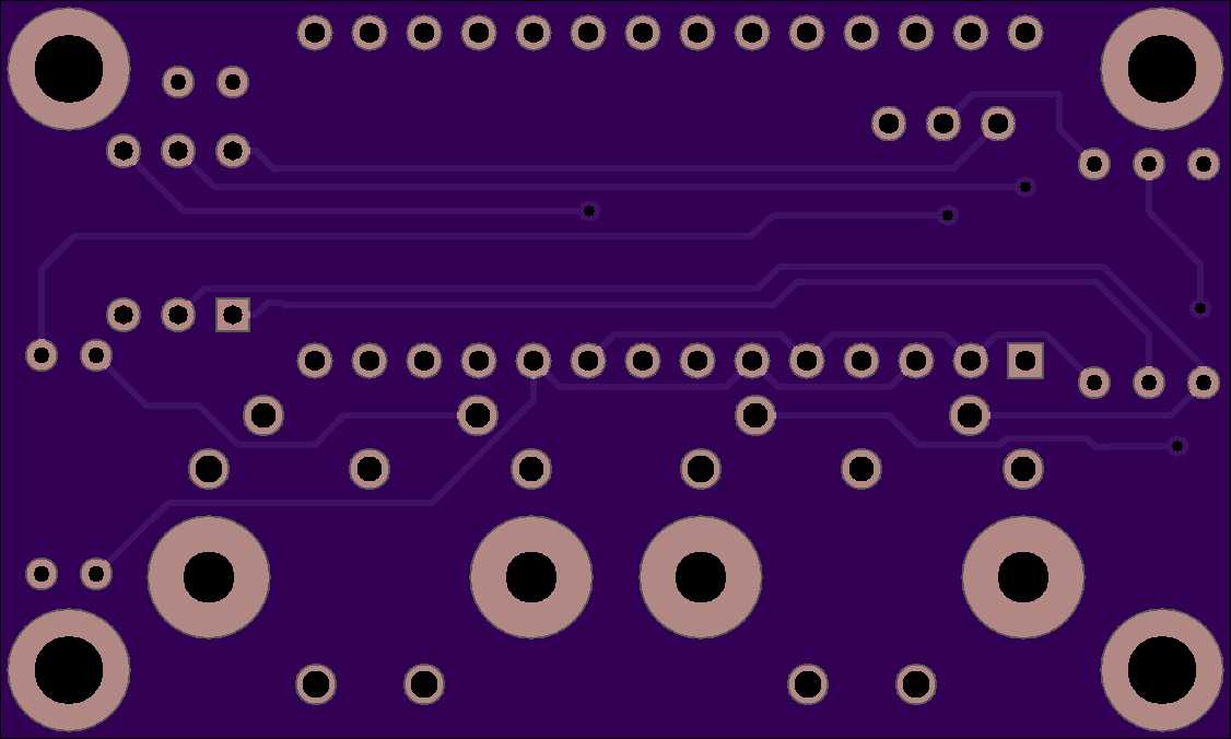
miditest2
by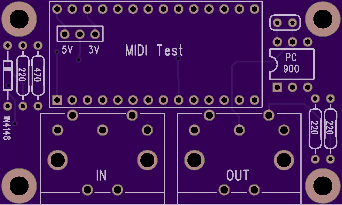
2
layer board of
2.25x1.35
inches
(57.23x34.37
mm).
Shared on
September 8th, 2014 19:05.
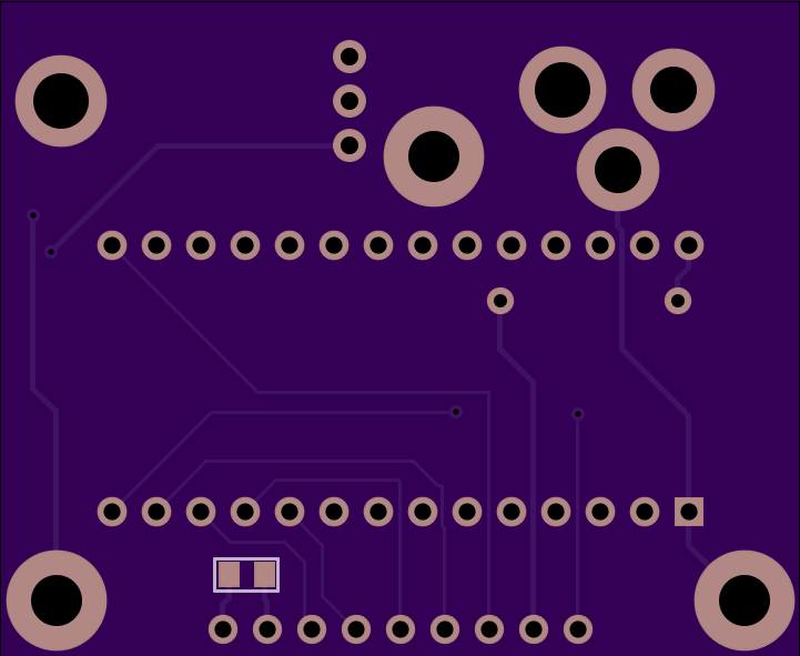
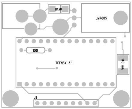
miditest2
ILI9431 Display (320x240) to Teensy 3.1
by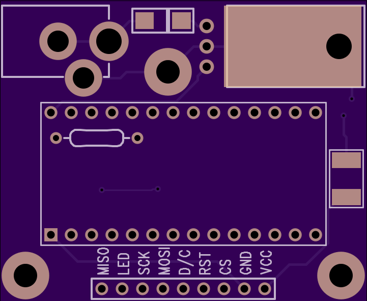
2
layer board of
1.80x1.48
inches
(45.77x37.54
mm).
Shared on
August 29th, 2014 19:32.
Newer Version Available
A new version of this board is available. It fixes problems with the reset signal and power jack.
You can easily identify the board version by the location of the 100 ohm resistor.
Old Info:
This is the little test board shown here:
http://www.pjrc.com/store/display_ili9341.html
Parts used on the board are:
    LM7805 voltage regulator        Digikey LM7805ACT-ND
    B130 Schottky diode             Digikey B130-FDICT-ND
    140 mA PTC fuse                 Digikey 507-1495-1-ND
    100 ohm 1/4 watt resistor       Digikey 100XBK-ND
    DC power jack                   Mouser 163-7620E-E
    1uF 0805 capacitor              Digikey 1276-1066-1-ND
This PCB has the display RST signals connected to pin 8, not 3.3V. This special step is needed to make it work.
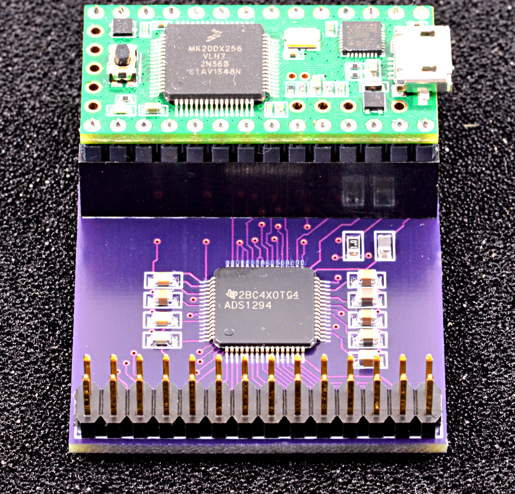
biopotential
by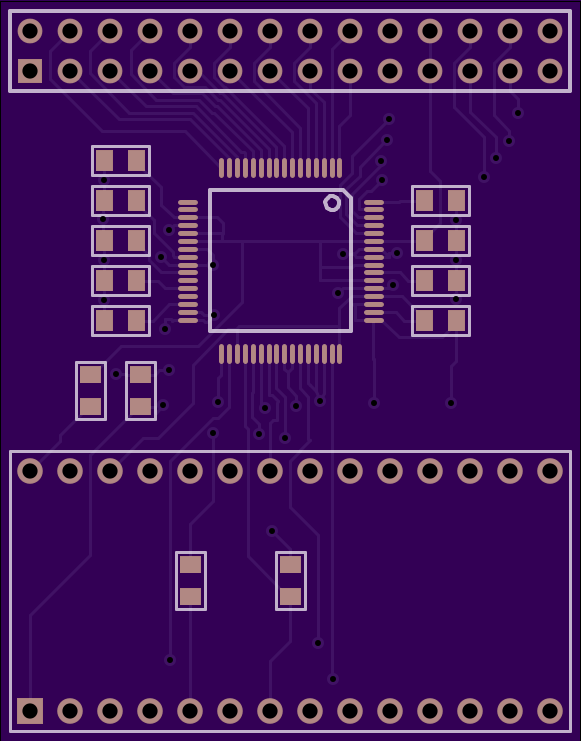
2
layer board of
1.45x1.85
inches
(36.88x47.07
mm).
Shared on
August 13th, 2014 21:45.
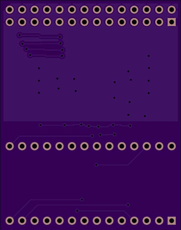
rfm69_adaptor3
by
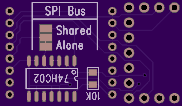
2
layer board of
1.20x0.70
inches
(30.53x17.86
mm).
Shared on
July 27th, 2014 17:24.
rfm69_adaptor3
Documentation on prior version:
rfm69_adaptor2
by
2
layer board of
1.20x0.70
inches
(30.53x17.86
mm).
Shared on
April 25th, 2014 21:09.
Connections:
    Teensy 3.x       RFM69
    ------------     ------
    pin 15 (CS)      NSS (Chip Select)
    pin 16           DIO0 (interrupt)
    pin 11 (DOUT)    MOSI
    pin 12 (DIN)     MISO
    pin 13 (SCK)     SCK
    3.3V             3.3V
    GND              GND
Detailed Tutorial: Adding A Low Cost Wireless Packet Radio To A Teensy 3 Microprocessor (PDF)
When using the RadioHead library, edit the Arduino sketch examples to specify pins 15 and 16. For example:
    // Singleton instance of the radio driver
    RH_RF69 rf69(15, 16);
Discussion and more documentation for this adaptor can be found here:
http://forum.pjrc.com/threads/25897-Adapter-board-RFM69W-radio-for-Teensy-3-Also-diagnostic-software
A newer version of this PCB was designed, with the ability to disable the SPI SCK signal (possibly causing RF interference on the RFM69 module), but so far it is untested.