OSH Park
Profile for PaulStoffregen
Shared projects
I/O Expander for LED Arcade Buttons
by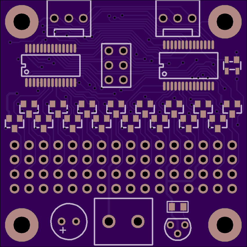
2
layer board of
1.70x1.70
inches
(43.23x43.23
mm).
Shared on
May 24th, 2017 18:22.
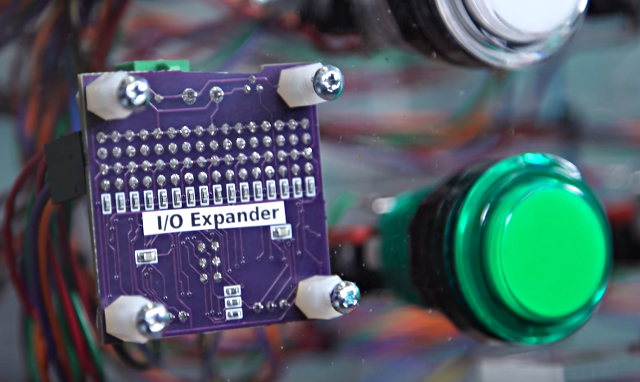
I/O Expander
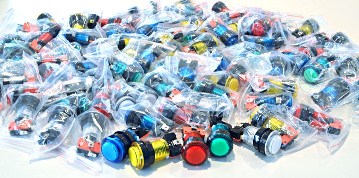
The Monolith Synth Project needed to use a large number of these LED lit arcade buttons.
Dimming of the LEDs was required. Initially I considered using this Adafruit 16 Channel PWM board. But the LEDs in these buttons have integrated resistors which require 12 volts, so 16 transistor circuits and another board for reading the switches would have also been needed.
Instead I designed this board with everything required on a single small size board.
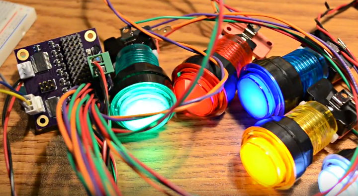
It uses the same PCA9685 chip for 12 bit PWM control on every LED, with mosfet drivers to handle 12V outputs, and also a MCP23017 chip to read the buttons. Every button has a discrete 1K pullup resistor (rather than using the higher impedance on-chip pullups) to help with use in the same cable bundles cross coupling to 12V PWM signals.
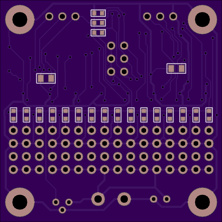
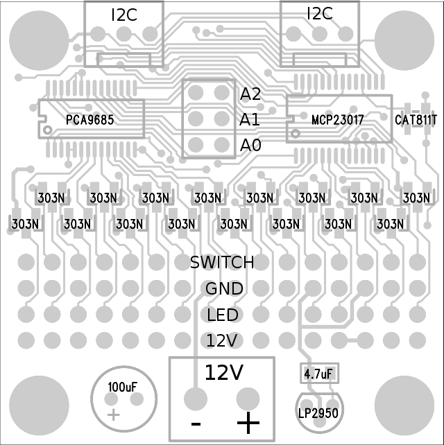
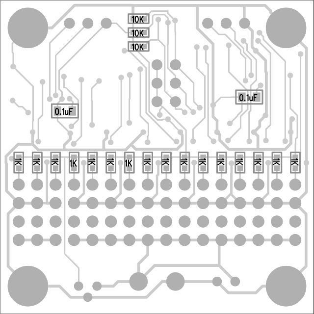
Parts Placement
Bill Of Materials
 1   MCP23017 16 bit GPIO                   MCP23017-E/SS-ND
 1   PCA9685 16 channel PWM                 568-11925-1-ND
 1   LP2950-5V LDO Voltage Regulator        296-20933-1-ND
 1   CAT811T Reset Chip                     CAT811TTBI-GT3OSTR-ND
16   FDV303N N-Ch Mosfet                    FDV303NCT-ND
 4   Header, 16x1                           609-3256-ND
 1   Header, 3x2                            67996-206HLF
 2   Connector, Molex 3 pin                 WM4201-ND
 1   Connector, Terminal Block 2 pin        277-1150-ND
 2   Capacitor, 0.1uF, 805                  478-1395-1-ND
 1   Capacitor, 4.7uF, 805                  490-6479-1-ND
 1   Capacitor, 100uF (10-47uF is ok)       399-6648-1-ND
16   Resistor, 1K, 603                      311-1.00KHRCT-ND
 3   Resistor, 10K, 603                     311-10.0KHRCT-ND
Mating Connectors
16   Housing, 4 position                    952-2229-ND
64   Crimp contact                          952-2158-ND
 1   Terminal Block, 2 position             277-1011-ND
 2   Housing, Molex 3 position              WM2001-ND
 6   Cript contact                          WM1114-ND
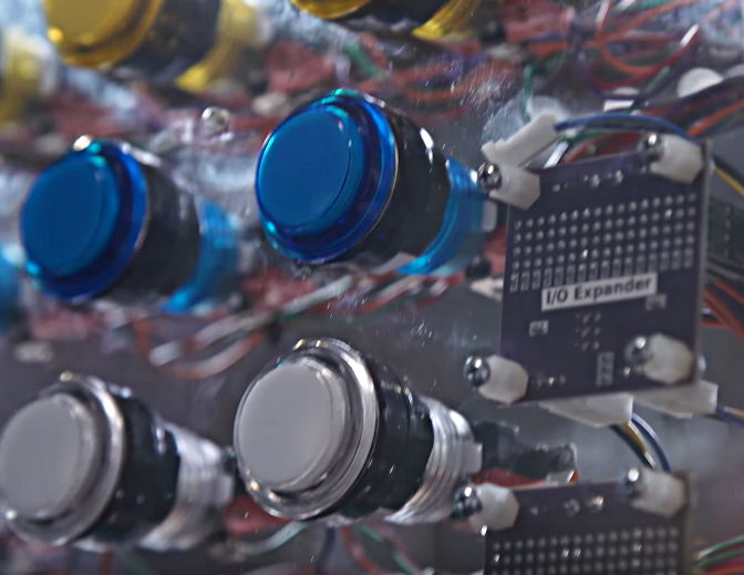
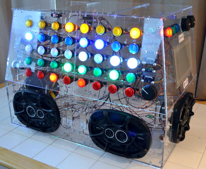
Monolith Synth
Four of these boards where used in the Monolith Synth project, shown at Tested and Bay Area Maker Faire 2017.
CS42448 Audio, 6 Inputs, 8 Outputs
by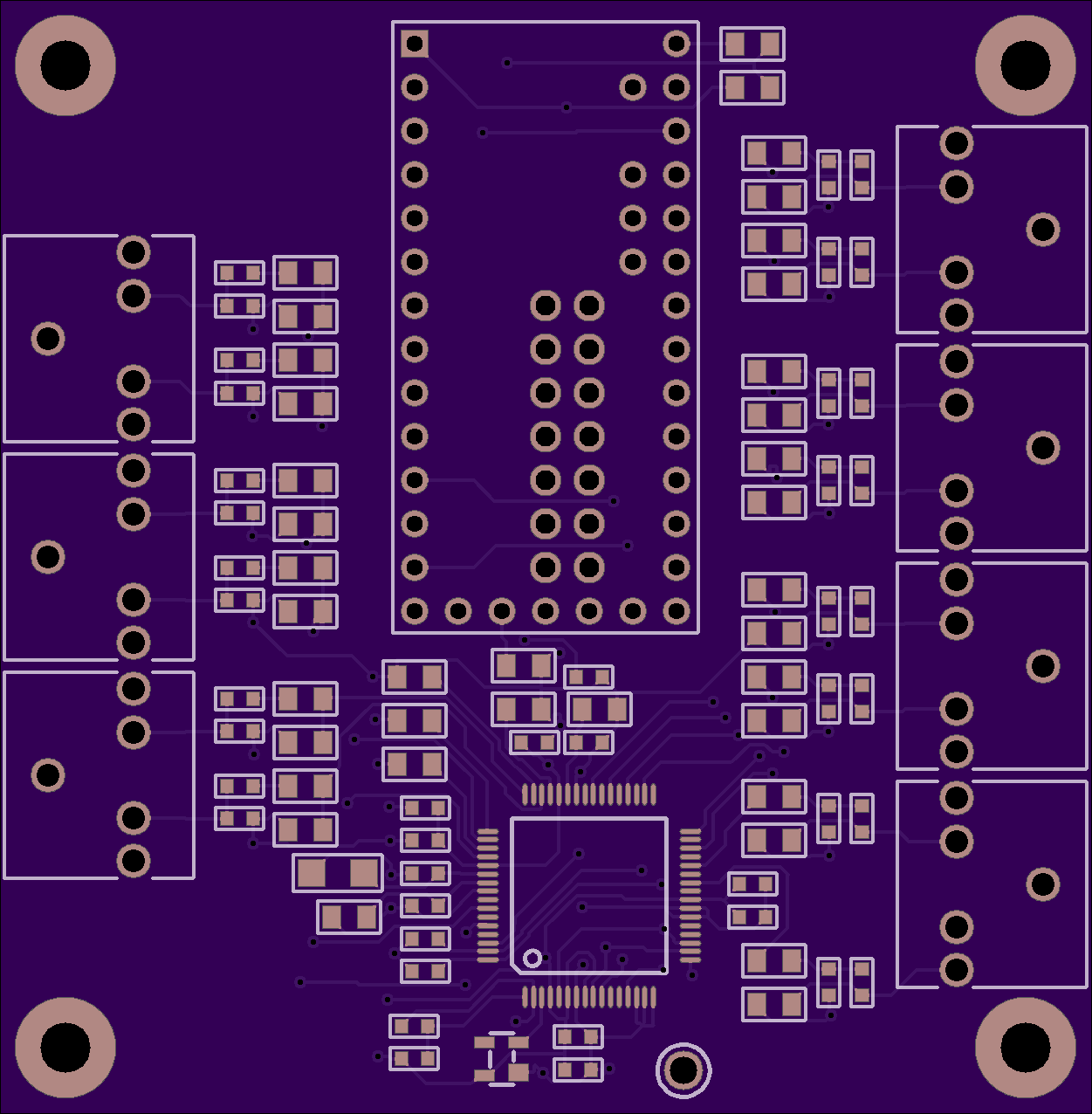
2
layer board of
2.50x2.55
inches
(63.55x64.82
mm).
Shared on
April 17th, 2017 20:23.
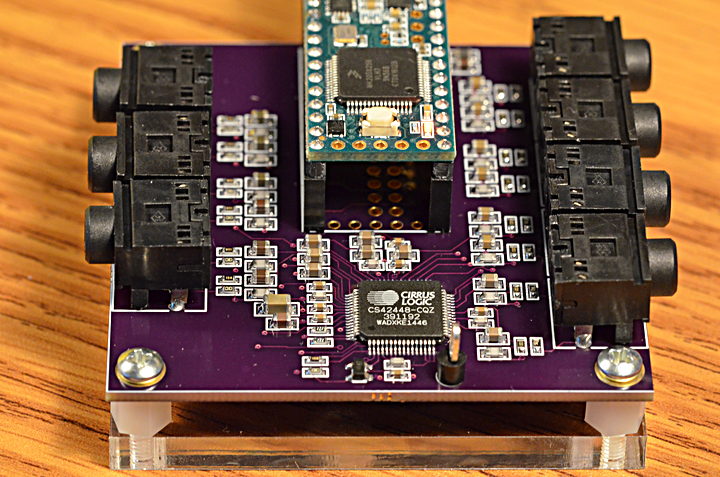
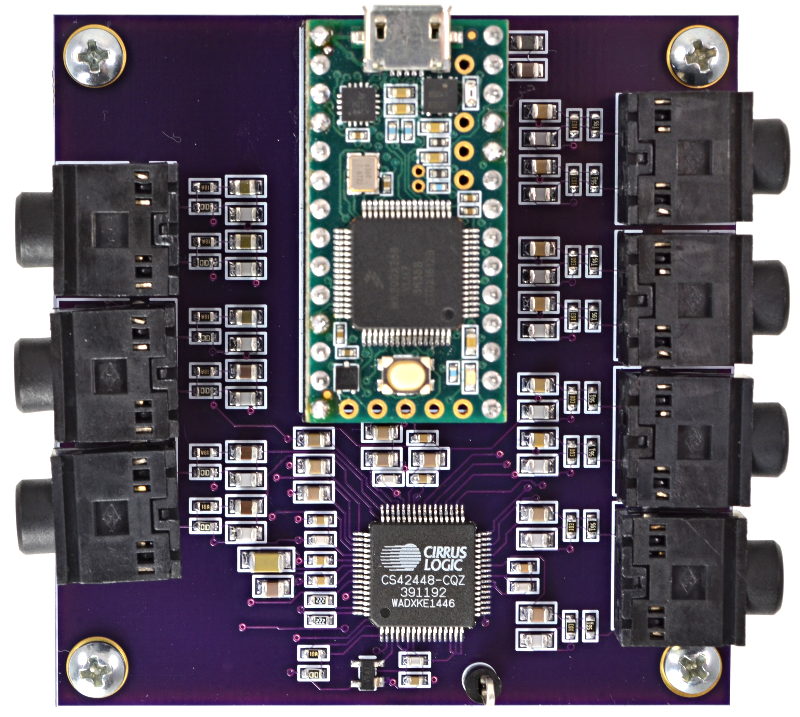
CS42448 Audio
Some projects need a lot of audio I/O. Maybe you’re doing positional audio sound effects (using the 8-tap delay effect) where ordinary stereo or even 5 channel “surround” isn’t enough? Maybe you’re making the ultimate Eurorack synthesizer module? Or you just want a lot of signals, because you can!
Here’s a board for the Cirrus Logic CS42448 chip, which provides 6 inputs and 8 outputs. All are high quality audio, and all work simultaneously.
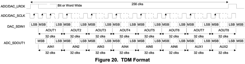
TDM Data Interface
Normally digital audio is communicated between chips using I2S protocol (which is different than I2C, despite the similar acronym). Two I2S streams can be used for quad channel, but to really step up to more channels, you need TDM protocol.
TDM communicates a frame of 256 data bits. For 44.1 kHz, this means the bit clock must be 11.3 MHz. Only 4 signals are used, one to transmit all 256 bits and another to receive all 256, a frame sync signal the marks where each 256 bit frame begins, and of course the 11.3 MHz clock.
Here is the TDM waveform documented by Cirrus Logic for the CS42448 chip.
Actual TDM Signals
When viewed on an oscilloscope, here is how the TDM signal actually appears:
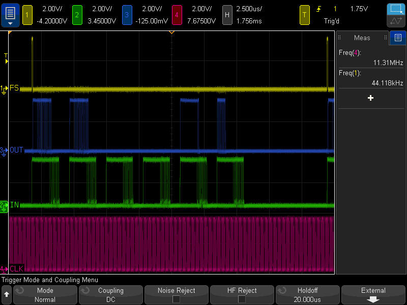
During this test, the code below was running. The output from Teensy is the blue trace. It sends a 16 bit guitar synthesis to CS42448 AOUT1 & AOUT2. Because the CS42448 outputs are 32 bits, but the audio is only 16 bits you can see the lower 16 bits are always zero. Most of the rest of the output is zeros, except this example also brings in AIN1 and sends its top 16 bits to AOUT5 and its lower 16 bits to AOUT6.
Of course, the green trace is the data being received from the CS42448. All 6 inputs were left unconnected. Even through the channel slots of 32 bits, the CS42448 only produces 24 bits of data, and its lower 8-9 bits are mostly random noise. This PCB uses only the simplest single-ended input circuit. The better opamp-based differential circuit documented in the CS42448 could be expected to improve performance.
Software Support
TDM support has recently been added to the Teensy Audio Library. It’s accessed by creating AudioInputTDM and AudioOutputTDM objects.
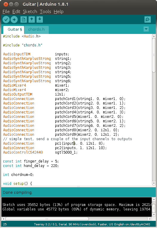
Each AudioInputTDM creates 16 simultaneous inputs. Like all communication in the Teensy Audio Library, the data is 16 bits wide. 16 of these channels gives access to all 256 incoming TDM bits. For CS42448, only channels 0, 2, 4, 6, 8 & 10 would be really useful.
Likewise, each AudioOutputTDM object can accept 16 simultaneous 16 bit audio streams, to fully control all 256 bits of the TDM output frame. For CS42448, only the 8 even numbered channels are useful.
Development of the audio software support is being discussed on this forum thread. If you make one of these boards, please join the conversation!
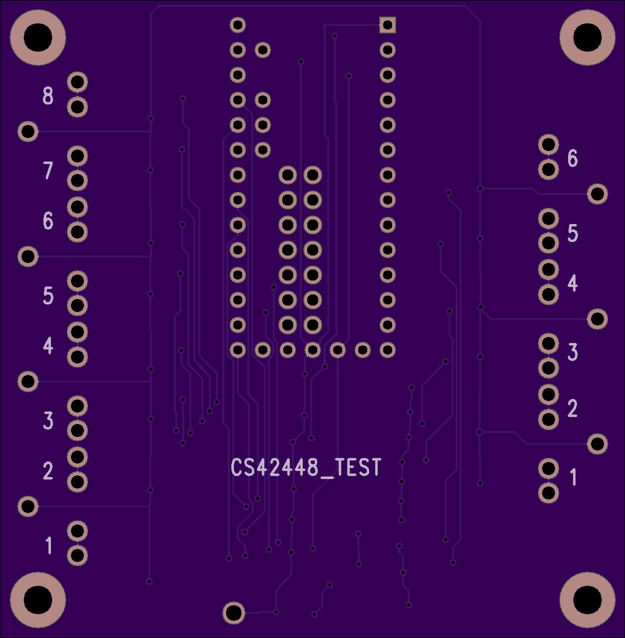
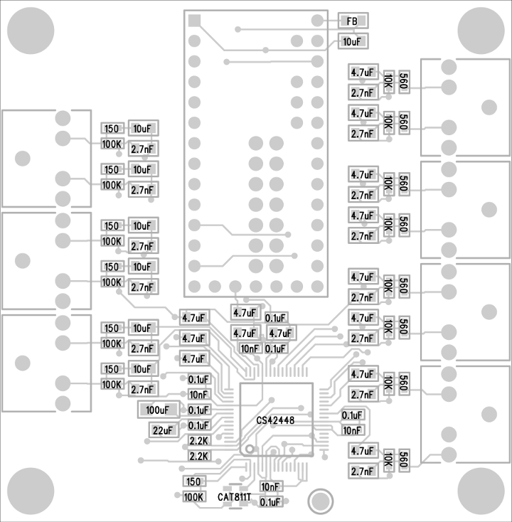
Parts Placement Diagram
Bill Of Materials
 1   CS42448, Codec Chip            598-1033-ND
 1   CAT811T, Reset Chip            CAT811TTBI-GT3OSCT-ND
 7   Connector, audio               CP1-3525N-ND
 7   Resistor, 150 ohm, 603         311-150HRCT-ND
 8   Resistor, 560 ohm, 603         RMCF0603FT560RCT-ND
 2   Resistor, 2.2K ohm, 603        311-2.20KHRCT-ND
 8   Resistor, 10K ohm, 603         311-10.0KHRCT-ND
 7   Resistor, 100K ohm, 603        311-100KHRCT-ND
14   Capacitor, 2.7nF, NP0, 805     445-7508-1-ND
 4   Capacitor, 10nF, X7R, 603      490-1512-1-ND
 7   Capacitor, 0.1uF, X7R, 603     490-1524-1-ND
14   Capacitor, 4.7uF, X5R, 805     1276-6463-1-ND
 7   Capacitor, 10uF, X5R, 805      399-4925-1-ND
 1   Capacitor, 22uF, X5R, 805      490-1719-1-ND
 1   Capacitor, 100uF, X6T, 1206    490-10525-1-ND
 1   Inductor, Ferrite Bead, 805    490-1054-1-ND
 1   Teensy 3.2, 3.5 or 3.6         www.pjrc.com/store/teensy32.html
 2   Socket, 14x1                   www.pjrc.com/store/socket_14x1.html
 2   Header, 14x1                   www.pjrc.com/store/header_14x1.html
 1   Heatsink                       (optional: CS42448 runs hot)
PT8211 Audio Shield
by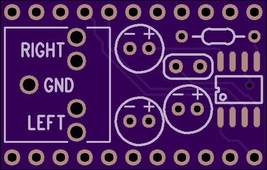
2
layer board of
1.10x0.70
inches
(27.97x17.83
mm).
Shared on
April 5th, 2017 17:27.
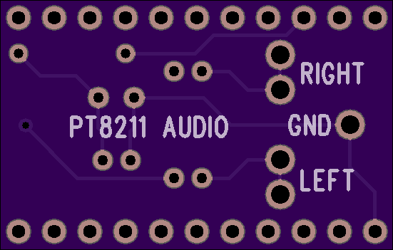
PT8211 Audio Shield
PT8211 is an inexpensive 16 bit stereo DAC.
This small breakout board connects the PT8211 to Teensy 3.2, Teensy 3.5 or Teensy 3.6.
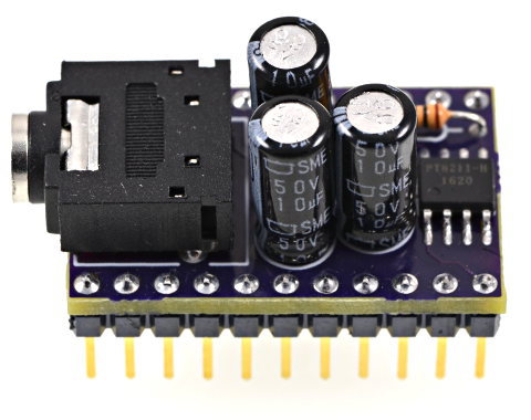
Detailed soldering steps are shown on the PJRC product page, where this PCB is sold as part of a DIY soldering kit. Of course, you can also get the bare PCB here on OSH Park if you like.
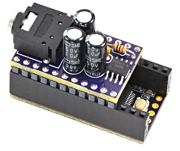
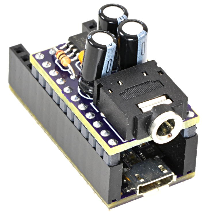
Here is the assembly with the PT8211 on a purple OSH Park Edition Teensy 3.2.
Bill Of Materials
1   PT8211 chip                Ebay merchants
1   Audio connector, 3.5mm     CP1-3525N-ND
1   10 ohm resistor            10EBK-ND
3   47 uF capacitor            493-15997-ND
1   0.1 uF capacitor           BC1084CT-ND
Almost any 5mm diameter aluminum electrolytic capacitor with 2mm lead spacing can work. While 47uF is recommended, you can see in the photos I built the first prototype using only 10uF (because they were in my spare parts drawer). Either works fine.
The PT8211 chip is very inexpensive, sold by many shady Ebay merchants from Hong Kong at very low prices. There doesn’t seem to be any sure way to buy this part, but just searching for “PT8211” on Ebay brings up many sellers.
Software Support
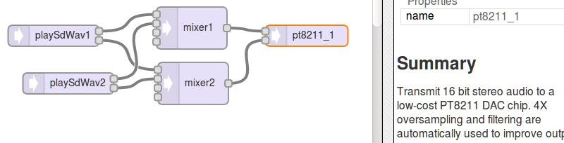
PT8211 is supported by the Teensy Audio Library.
You can simply drag the PT8211 onto the Design Tool canvas and connect it into your audio system, and of course click “Export” to generate the Arduino code.
It’s also possible to edit any of the audio library examples, which are designed for the Teensy Audio Shield. With Teensy selected in Tools > Boards, just click Arduino’s File > Examples > Audio menu to find dozens of examples. To convert these, just find AudioOutputI2S in the code and change it to AudioOutputPT8211.
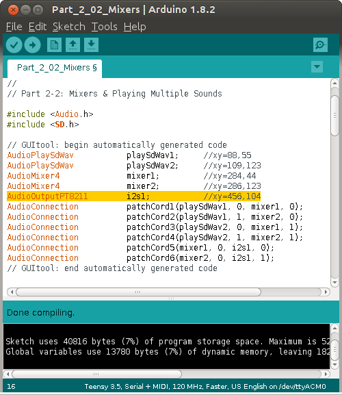
Also delete any AudioControlSGTL5000 objects and code using them. The PT8211 is a very simple chip without any configurable parameters. You just send it digital audio and it turns the data into analog signals. Simple!
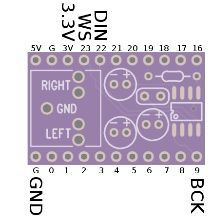
PT8211 Signals
Signal     Teensy Pin     PT8211 Pin
------     ----------     ----------
 BCK            9              1
 DIN           22              3
 WS            23              2
 +3.3V       3.3V              5
 GND          GND              4
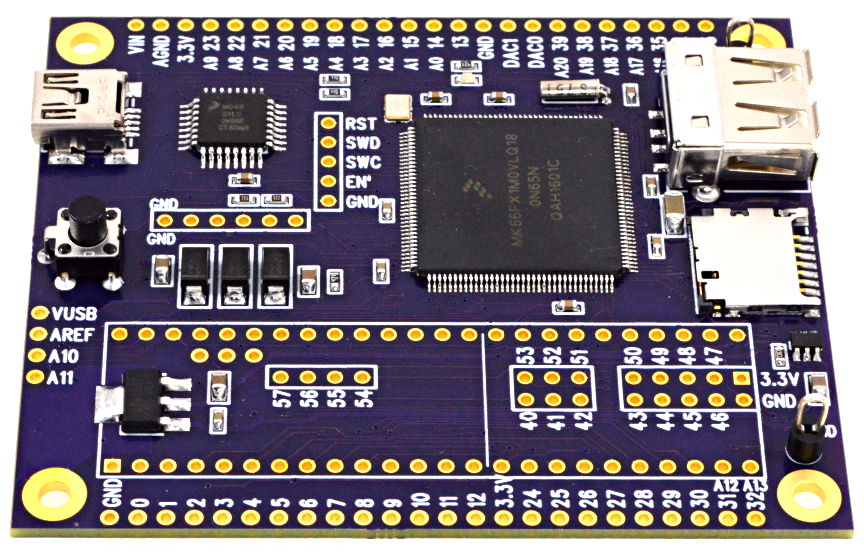
Teensy 3.6 DIY Reference Board
by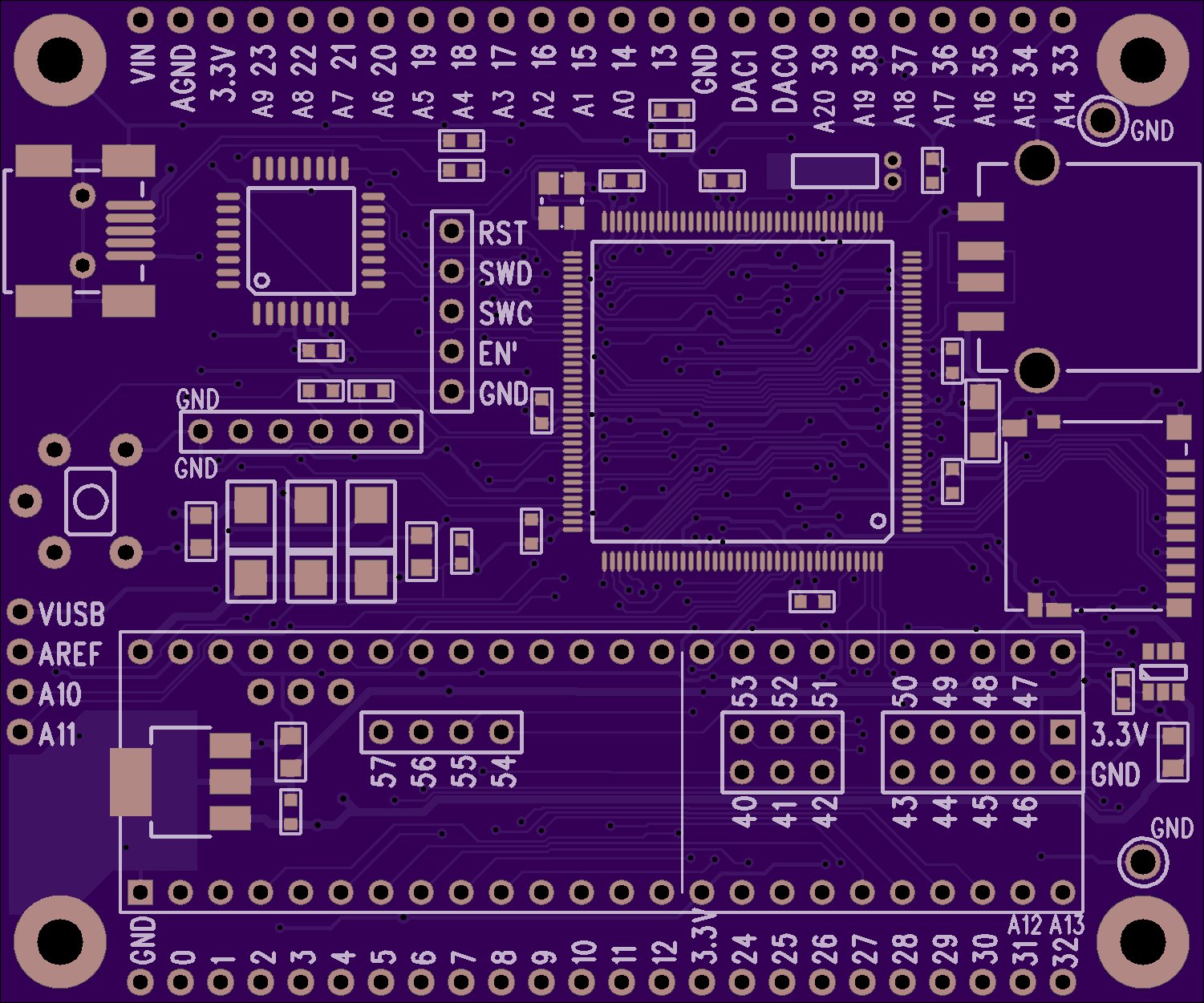
2
layer board of
3.00x2.50
inches
(76.28x63.58
mm).
Shared on
March 10th, 2017 18:11.
A known good reference board for testing the MKL04 chip when building a DIY Teensy 3.6. Refer to this table for the differences between Teensy 3.6 and other models. The soldering friendly LQFP package (at least more friendly than BGA) is used on this board.
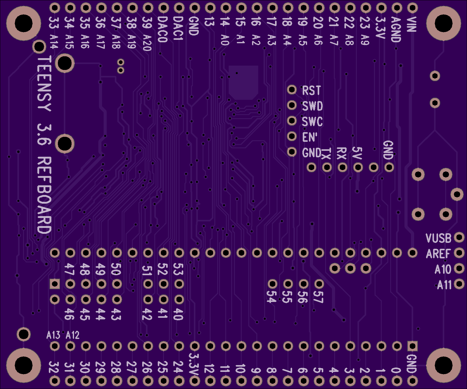
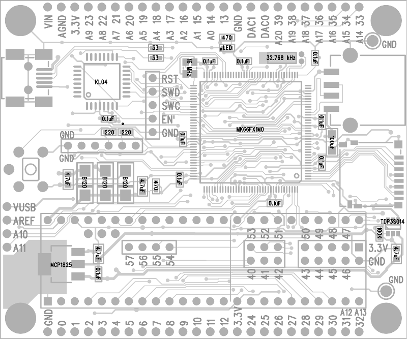
Parts Placement Diagram
Bill Of Materials
1   MK66FX1M0VLQ18
1   IC_MKL04Z32_TQFP32
1   USB A Connector
1   USB Mini B Connector
1   Micro SD Socket
1   MCP1825S Voltage Regulator
1   TPD3S014 USB Power Switch
1   Crystal, 16 MHz
1   Crystal, 32.768 kHz
3   Diode, Schottky, B120
1   Capacitor, 100uF, 6.3V
4   Capacitor, 4.7uF
10  Capacitor, 0.1uF
1   Resistor, 100K
2   Resistor, 470
2   Resistor, 220
2   Resistor, 33
1   Pushbutton
2   Test Point, Black
TODO: Add part numbers…
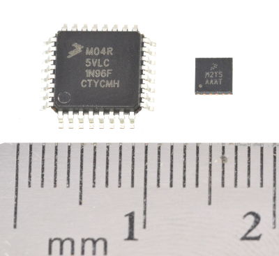
Bootloader Chip
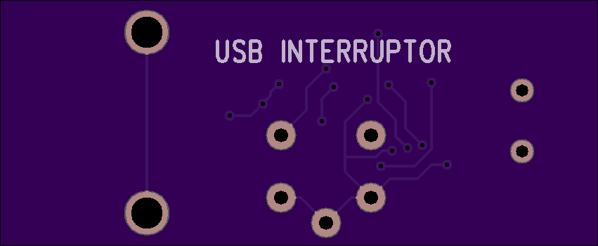
USB Interruptor
by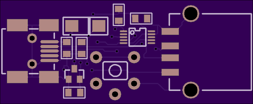
2
layer board of
1.70x0.70
inches
(43.23x17.83
mm).
Shared on
February 25th, 2017 14:04.
USB Interruptor
This simple board plugs inline with a USB cable. It always passes the 5V power and normally passes the USB data signals. But when you press the button, the signals are momentarily disconnected.
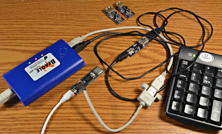
Why would anyone want or need such a things? Well, for the last few months I’ve been developing a USB Host Library for powerful but complex EHCI USB port in Teensy 3.6. After several false starts and re-reading the USB 2.0 and EHCI 1.0 specs and datasheet over and over (did I mention this 480 Mbit/sec USB host port is powerful but really complex), it’s finally starting to come together.
Now I’m at the stage where it’s time to begin work on code to handle USB disconnect events. When you unplug the cable, the ECHI work queues need to be removed, periodic schedule bandwidth allocation/planning needs to be undone, memory needs to be freed (hopefully it’s all findable from linked lists), hub/port status needs to be updated, and probably a ton of other stuff needs to happen that I haven’t even considered yet…
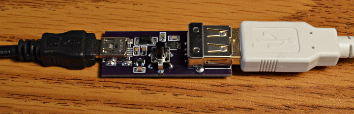
Reaching over to physically unplug the USB cable gets old quickly! Really, really old, both hands off my keyboard… right when trying to focus. With 12 Mbit/sec USB ordinary switches can usually work, but this is 480 Mbit/sec and I’m already running it through a USB protocol analyzer and a few cables plugged in tandem, leaving not much signal quality margin left. So I made this handy little board with a proper USB 2.0 high speed mux chip. The control signal is just 3.3V logic, so I might even wire it up to something to automate the process.
Admittedly, not many people develop USB host drivers and software stacks (it’s turning out to be probably the toughest coding I’ve ever done), so this little board might not have really wide applications. But here’s all the details anyway. ;-)
Update: check out this similar board, using slightly different parts.
Parts Placement
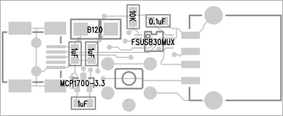
Bill Of Materials
1 Resistor, 10K, 805 RHM10.0KCHCT-ND
1 Capacitor, 0.1uF, 805 478-1395-1-ND
3 Capacitor, 1uF, 805 587-1281-1-ND
1 Diode, Schottky, B120 B120-E3/5ATGICT-ND
1 MCP1700 3.3V regulator MCP1700T3302ETTCT-ND
1 FSUSB30 USB Mux Switch FSUSB30MUXCT-ND
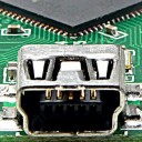
1 USB Connector, Mini-B 609-4701-1-ND
1 USB Connector, Std A ED90065-ND
1 Pushbutton P8016S-ND