
OSH Park
Profile for Pawelsky
Shared projects
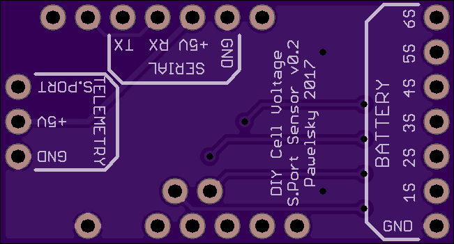
DIY Cell Voltage S.Port Sensor v0.2
by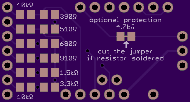
2
layer board of
1.30x0.70
inches
(33.02x17.81
mm).
Shared on
February 11th, 2017 12:45.
HARDWARE


Credit goes to MCfuturegame .. for the Arduino Pro Mini model used in the above rendering.
Required components:
- Arduino Pro Mini 328P/16MHz/5V (with standard Arduino pinout for A4/A5 ports)
- resistors in 0805 package: 6 * 10k, 1 * 390ohm, 1 * 510ohm, 1 * 680ohm, 1 * 910ohm, 1 * 1.5k, 1 * 3.3k (and optionally 1 * 4.7k for protecting the 3.3V S.Port line from 5.0V Arduino serial - cut the jumper between solder pads if you install this resistor)
- 1 * 1x9 straight 2.54mm header pins (divided into 1, 1, 2, 5 sections)
- 1 * 1x14 right angle 2.54mm header pins (divided into 3, 4, 7)
NOTE 1: the 4 pin SERIAL connection is optional and used for uploading the code only - you don’t have to solder it in permanently. Make sure you always connect it TO THE SHIELD, not to the Arduino board itself! When uploading the code the Arduino board needs to be reset manually using the reset button.
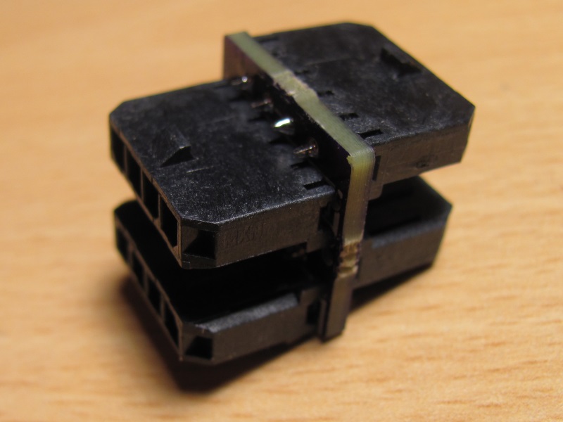
NOTE 2: make sure you order the right angle pin headers that install flat on the board (see the picture below).

SOFTWARE
Load the code below (requires FrSky S-Port Telemetry and standard SoftwareSerial libraries)
/*
  DIY Cell Voltage S-Port Sensor
  (c) Pawelsky 20160123
  Not for commercial use
*/

#include "FrSkySportSensor.h"
#include "FrSkySportSensorFlvss.h"
#include "FrSkySportSingleWireSerial.h"
#include "FrSkySportTelemetry.h"
#include "SoftwareSerial.h"

FrSkySportSensorFlvss flvss;
FrSkySportTelemetry telemetry;

float cell1DividerMultiplier = (10000.0 + 3300.0) / 3300.0 * 1.1 / 1023.0;
float cell2DividerMultiplier = (10000.0 + 1500.0) / 1500.0 * 1.1 / 1023.0;
float cell3DividerMultiplier = (10000.0 +  910.0) /  910.0 * 1.1 / 1023.0;
float cell4DividerMultiplier = (10000.0 +  680.0) /  680.0 * 1.1 / 1023.0;
float cell5DividerMultiplier = (10000.0 +  510.0) /  510.0 * 1.1 / 1023.0;
float cell6DividerMultiplier = (10000.0 +  390.0) /  390.0 * 1.1 / 1023.0;

float cell1Voltage = 0.0;
float cell2Voltage = 0.0;
float cell3Voltage = 0.0;
float cell4Voltage = 0.0;
float cell5Voltage = 0.0;
float cell6Voltage = 0.0;

void setup()
{
  pinMode(A0, INPUT);
  pinMode(A1, INPUT);
  pinMode(A2, INPUT);
  pinMode(A3, INPUT);
  pinMode(A4, INPUT);
  pinMode(A5, INPUT);
  analogReference(INTERNAL);
  telemetry.begin(FrSkySportSingleWireSerial::SOFT_SERIAL_PIN_4, &flvss);
}

void loop()
{
  cell1Voltage = (float)analogRead(A5) * cell1DividerMultiplier;
  cell2Voltage = (float)analogRead(A4) * cell2DividerMultiplier;
  cell3Voltage = (float)analogRead(A3) * cell3DividerMultiplier;
  cell4Voltage = (float)analogRead(A2) * cell4DividerMultiplier;
  cell5Voltage = (float)analogRead(A0) * cell5DividerMultiplier;
  cell6Voltage = (float)analogRead(A1) * cell6DividerMultiplier;
  flvss.setData(cell1Voltage, cell2Voltage - cell1Voltage, cell3Voltage - cell2Voltage,
                cell4Voltage - cell3Voltage, cell5Voltage - cell4Voltage, cell6Voltage - cell5Voltage);
  telemetry.send();
}
This shield is meant for hobbyists and DIYers only. It has not been tested and there are no guarantees it will work. You can download the design file, modify it to your needs and build the board for yourself but you always use it at your own risk!
Not for commercial use!
Teensy 3.2 CAN + MicroSD + IO shield v0.2
by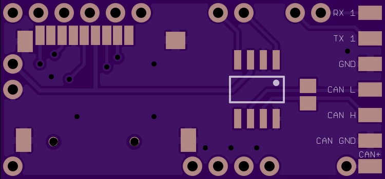
2
layer board of
1.50x0.70
inches
(38.13x17.81
mm).
Shared on
December 18th, 2016 16:46.
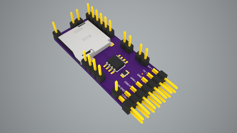
This Teensy 3.2 shield allows to communicate with the CAN bus with up to 1Mb/s speed. It includes the MicroSD push-push type slot to allow easy data logging. It does not have its own power regulator (which makes it cheaper and easier to build) and relies on Teensy 3.2 built in regulator providing up to 250mA for input voltages in the 3.6V-6V range. It also has place for up to 4 resistor dividers that increase the maximum voltage you can measure using the analog I/O pins.
Here is a RC Groups thread from which it has originated: http://www.rcgroups.com/forums/showpost.php?p=27129264&postcount=1
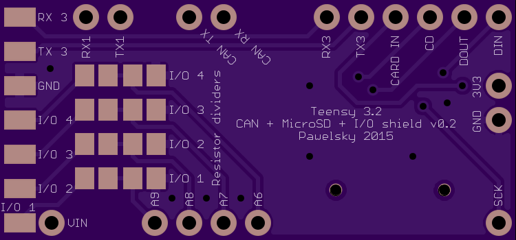
The shield has following pins broken out:
- CAN bus (CAN +, CAN GND, CAN H, CAN L)
- Serial ports (TX, RX and GND for Teensy’s Serial1 and Serial3)
- Analog pins (I/O1, I/O2, I/O3 and I/O4 mapped to Teensy’s A9, A8, A7 and A6 accordingly - optionally via a resistor divider)
- Note that pin 9 can be used for card detection (shorted to GND when card inserted, floating otherwise)
Following components are needed to assemble this board:
- 1 * TI SN65HVD230, SN65HVD231 or SN65HVD232 (recommended) CAN transceiver in the SOIC-8 package
- 1 * MicroSD card push-push type slot matching the Suntech ST-TF-003A or Adam Tech MCSP-08-C-SG dimensions
- 1 * 1x18 straight 2.54mm header pins (divided into 1, 1, 2, 2, 2, 4, 6 sections)
- 1 * 2x7 straight 2.54mm header pins
- 1 * 120ohm resitor in 0805 package (optional, only needed if you require CAN bus termination)
- 4 * resitor pair in 0805 package (optional, only needed if you require resistor dividers, resistor pair values depend on the division ratio you need to achieve - see below for some examples)
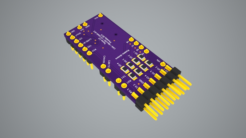
Here is how the shield looks like when assembled (notice the place for the optional terminating resistor next to the transceiver chip)
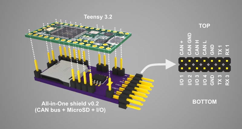
The below picture shows how the shield shall be stacked together with Teensy and also provides pins description.
Before soldering the shield to the Teensy board make sure the blink sketch is loaded to prevent setting used pins into the state that could damage the boards (e.g. setting pin 9 high when the Micro SD card is inserted would short it directly to GND).
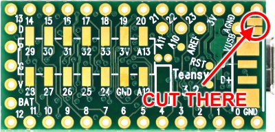
One important thing to remember when powering the Teensy with the shield is to not connect it to the USB when it is powered from the CAN bus. If for some reason you need to do it there are two options:
- Disconnect the CAN + wire
- Cut the VIN-VUSB pad at the bottom of Teensy (note that after you do that you’ll need to power Teensy from the CAN bus, or other external source every time when uploading a new sketch)
Resistor dividers
Each of the four I/O lines can have a resistor divider installed. The picture below shows which resistor belongs to which I/O line
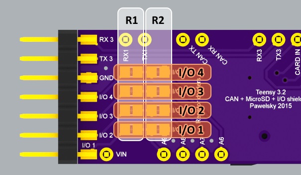
When no divider is used the R1 pads for a particular I/O line shall be soldered together and the R2 pads for the same line shall be left open. The maximum voltage that can be mesured without the divider is 3.3V.
When a divider needs to be used both R1 and R2 pads of a particular I/O line shall be populated with appropriate resistors.
Here are some example resistor values for typical RC world usage:
- R1 = 3.0kOhm, R2 = 4.7kOhm
max measured voltage = 5.4V (this is useful when measuring data form sensors that provide up to 5.0V output) - R1 = 22kOhm, R2 = 4.7kOhm
max measured voltage = 18.7V (this is useful when measuring voltage of battery packs up to 4S) - R1 = 22kOhm, R2 = 3.0kOhm
max measured voltage = 27.5V (this is useful when measuring voltage of battery packs up to 6S)
Note that these resistor values are calculated to be used with 3.3V analog reference voltage
From software perspective following libraries have been tested to work fine with this shield:
- For CAN bus - teachop’s FlexCan library
- For MicroSD - either Arduino’s built in SD library or gremain’s SdFat library
- For resistor dividers - Pawelsky’s ResistorDivider library
This shield is meant for hobbyists and DIYers only. Although this board has been used and tested for quite a while there are no guarantees it will work. You can download the design file, modify it to your needs and build the board for yourself but you always use it at your own risk!
Not for commercial use!
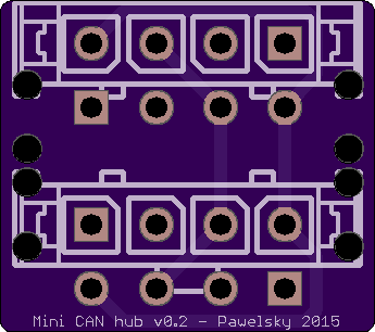
Mini CAN Hub v0.2
by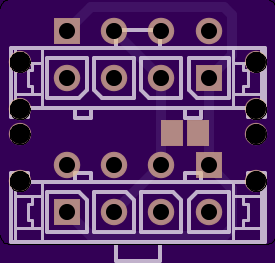
2
layer board of
0.69x0.61
inches
(17.50x15.52
mm).
Shared on
July 29th, 2015 10:50.
Mini CAN Hub v0.2 for DJI flight controllers
All you need to assemble this mini hub are 4 Molex Microfit 1x4 vertical PCB headers (43650-0427). When soldering the headers start with the two closer to the middle of the PCB (on both sides). Then solder the other two.
You can connect it to your controller using standard DJI CAN cable.
APM 2.6 GPS to Naza adapter v0.5
by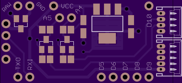
2
layer board of
1.45x0.70
inches
(36.83x17.78
mm).
Shared on
May 16th, 2015 13:49.
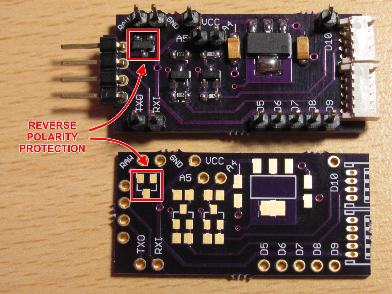
This is an enhanced version of APM 2.6 GPS to Naza adapter v0.4 that adds reverse polarity protection, so the module is not destroyed when the power plug is connected the wrong way.
The only difference compared to v0.4 is the addition of a P-Channel MOSFET (IRLML6401 in SOT-23 package) as on the picture below. Refer to the v0.4 description for assembly instructions and further details.
This shield is meant for hobbyists and DIYers only. Although this board has been used and tested for quite a while there are no guarantees it will work. You can download the design file, modify it to your needs and build the board for yourself but you always use it at your own risk!
Not for commercial use!
APM 2.6 GPS to Naza adapter v0.4
by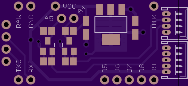
2
layer board of
1.45x0.70
inches
(36.83x17.78
mm).
Shared on
May 8th, 2015 19:37.
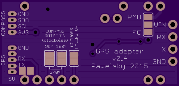
This Arduino Pro Mini shield allows to convert data coming from APM 2.6 GPS/compass combo into various other formats required.
One of the interesting examples is conversion into Naza (Lite/v1/v2) flight controller format, making it (together with a uBlox Neo 6M or Neo M8N and HMC5883L compass module) an alternative for the original Naza GPS puck.
More details about this particular conversion can be found in this RC Groups thread: http://www.rcgroups.com/forums/showpost.php?p=30011989&postcount=1
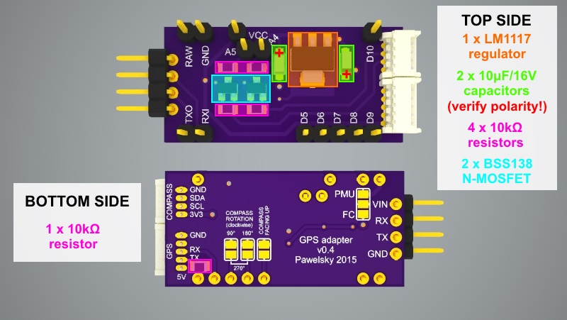
Following components are needed to assemble the adapter:
- 1 * TI LM1117 fixed 3.3V LDO regulator in SOT-223 package
- 2 * Tantalum 10uF/16V capacitors in SMD A package
- 2 * BSS138 N-MOSFET in SOT-23 package
- 5 * 10kΩ resitor in 0805 package
- 1 * 1x13 straight 2.54mm header pins (divided into 1, 1, 2, 2, 2, 5 sections)
- 1 * 1x4 right angle, low profile 2.54mm header pins (e.g. Adam Tech PH1RB)
- 1 * 4 pin Molex Picoblade 1.25 mm, right angle connector (MX-53048-0410)
- 1 * 5 pin Molex Picoblade 1.25 mm, right angle connector (MX-53048-0510)
- 1 * Arduino Pro Mini 16MHz/5V board (with Sparkfun compatible pinout - A4/A5 pins broken out next to A2/A3)
If you also want to add a reverse polarity protection (so the board is not fried when the power is connected the wrong way) you’ll need and additional P-Channel MOSFET and an enhanced (v0.5) version of the PCB. Details can be found HERE. Other than the extra MOSFET the rest of the board assembly is the same as below.
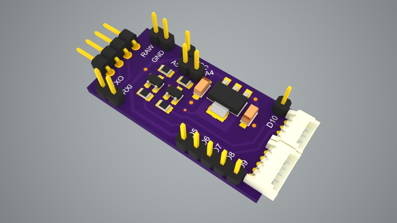
Here is how the shield looks like when assembled
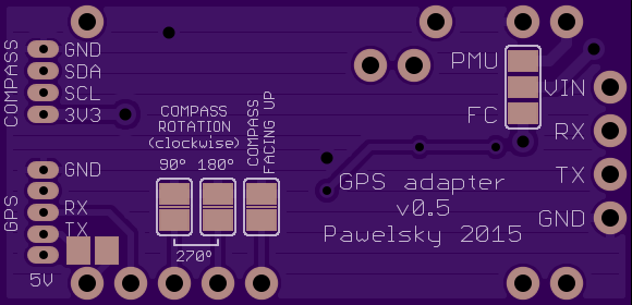
Picture below presents how the components are placed on the shield (both sides):
Note the VIN - PMU/FC solder pads at the bottom of the board. You should have these soldered in order for the adapter to work:
- when powering with 5V - solder VIN pad with FC pad
- when powering with more than 5V - solder VIN pad with PMU pad (note that in this case the Adrduino’s built in power regulator will be used to power everything so you must not exceed its voltage and current limitations)
Here you will find an explanation on where the “strange” FC/PMU naming convention comes from.
Here is how the shield shall be stacked together with Arduino Pro Mini board
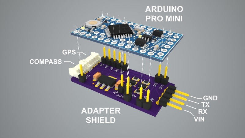
Credit goes to MCfuturegame .. for the Arduino Pro Mini model used in the above rendering.
This shield is meant for hobbyists and DIYers only. Although this board has been used and tested for quite a while there are no guarantees it will work. You can download the design file, modify it to your needs and build the board for yourself but you always use it at your own risk!