OSH Park
Teensy 3.2 CAN + MicroSD + IO shield v0.2
- You need to sign in or sign up before continuing.
Teensy 3.2 CAN + MicroSD + IO shield v0.2
by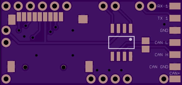
2
layer board of
1.50x0.70
inches
(38.13x17.81
mm).
Shared on
December 18th, 2016 16:46.
This Teensy 3.2 shield allows to communicate with the CAN bus with up to 1Mb/s speed. It includes the MicroSD push-push type slot to allow easy data logging. It does not have its own power regulator (which makes it cheaper and easier to build) and relies on Teensy 3.2 built in regulator providing up to 250mA for input voltages in the 3.6V-6V range. It also has place for up to 4 resistor dividers that increase the maximum voltage you can measure using the analog I/O pins.
Here is a RC Groups thread from which it has originated: http://www.rcgroups.com/forums/showpost.php?p=27129264&postcount=1
The shield has following pins broken out:
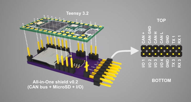
- CAN bus (CAN +, CAN GND, CAN H, CAN L)
- Serial ports (TX, RX and GND for Teensy’s Serial1 and Serial3)
- Analog pins (I/O1, I/O2, I/O3 and I/O4 mapped to Teensy’s A9, A8, A7 and A6 accordingly - optionally via a resistor divider)
- Note that pin 9 can be used for card detection (shorted to GND when card inserted, floating otherwise)
Following components are needed to assemble this board:
- 1 * TI SN65HVD230, SN65HVD231 or SN65HVD232 (recommended) CAN transceiver in the SOIC-8 package
- 1 * MicroSD card push-push type slot matching the Suntech ST-TF-003A or Adam Tech MCSP-08-C-SG dimensions
- 1 * 1x18 straight 2.54mm header pins (divided into 1, 1, 2, 2, 2, 4, 6 sections)
- 1 * 2x7 straight 2.54mm header pins
- 1 * 120ohm resitor in 0805 package (optional, only needed if you require CAN bus termination)
- 4 * resitor pair in 0805 package (optional, only needed if you require resistor dividers, resistor pair values depend on the division ratio you need to achieve - see below for some examples)
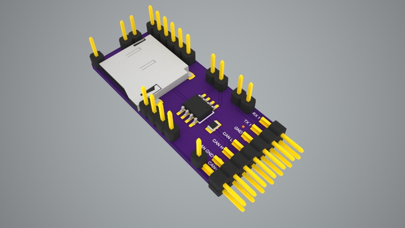
Here is how the shield looks like when assembled (notice the place for the optional terminating resistor next to the transceiver chip)
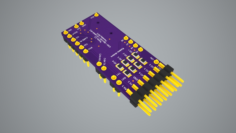
The below picture shows how the shield shall be stacked together with Teensy and also provides pins description.
Before soldering the shield to the Teensy board make sure the blink sketch is loaded to prevent setting used pins into the state that could damage the boards (e.g. setting pin 9 high when the Micro SD card is inserted would short it directly to GND).
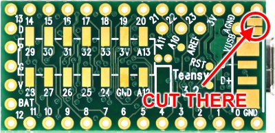
One important thing to remember when powering the Teensy with the shield is to not connect it to the USB when it is powered from the CAN bus. If for some reason you need to do it there are two options:
- Disconnect the CAN + wire
- Cut the VIN-VUSB pad at the bottom of Teensy (note that after you do that you’ll need to power Teensy from the CAN bus, or other external source every time when uploading a new sketch)
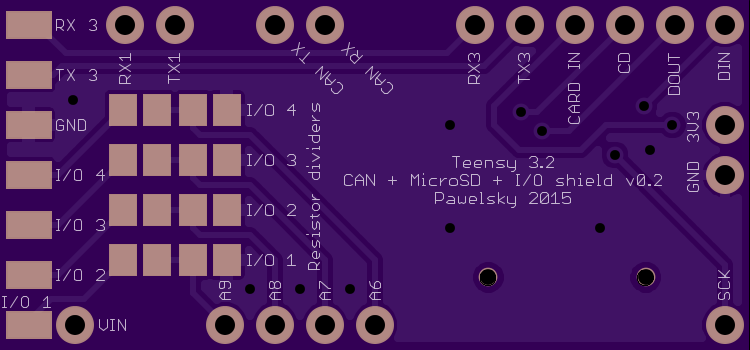
Resistor dividers
Each of the four I/O lines can have a resistor divider installed. The picture below shows which resistor belongs to which I/O line
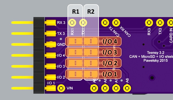
When no divider is used the R1 pads for a particular I/O line shall be soldered together and the R2 pads for the same line shall be left open. The maximum voltage that can be mesured without the divider is 3.3V.
When a divider needs to be used both R1 and R2 pads of a particular I/O line shall be populated with appropriate resistors.
Here are some example resistor values for typical RC world usage:
- R1 = 3.0kOhm, R2 = 4.7kOhm
max measured voltage = 5.4V (this is useful when measuring data form sensors that provide up to 5.0V output) - R1 = 22kOhm, R2 = 4.7kOhm
max measured voltage = 18.7V (this is useful when measuring voltage of battery packs up to 4S) - R1 = 22kOhm, R2 = 3.0kOhm
max measured voltage = 27.5V (this is useful when measuring voltage of battery packs up to 6S)
Note that these resistor values are calculated to be used with 3.3V analog reference voltage
From software perspective following libraries have been tested to work fine with this shield:
- For CAN bus - teachop’s FlexCan library
- For MicroSD - either Arduino’s built in SD library or gremain’s SdFat library
- For resistor dividers - Pawelsky’s ResistorDivider library
This shield is meant for hobbyists and DIYers only. Although this board has been used and tested for quite a while there are no guarantees it will work. You can download the design file, modify it to your needs and build the board for yourself but you always use it at your own risk!