
OSH Park
Profile for Texas_Ace
Shared projects
17mm V2 Texas Commander Tiny85
by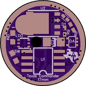
2
layer board of
0.68x0.68
inches
(17.15x17.15
mm).
Shared on
March 30th, 2017 14:17.
Ok, I don’t have time for my normal long post explaining every little detail of this driver. Plus with all the advancements coming down the line in driver tech I see bigger and better things coming out this year anyways.
Still this is a good concept and works great so it is worth posting it up.
Basically while this was not the goal, this is an open source LD-3 driver. The difference being that the LD-3 has a better 4 layer PCB and can handle a bit more heat then this driver. The features and basic setup are similar though. This driver also offers the ability to run bistro, which was the biggest reason for making it.
If you like the LD-3 firmware, just buy that and save yourself the time of building a driver by hand.
The credit design of the driver goes to DEL, he did all the technical design work, I just crammed it onto a 17mm driver and made his life harder by demanding every possible option be included. ^:)
So lets start off with the features of this driver:
It offers true constant current regulation without PWM It has a very low dropout voltage, which means it will maintain regulation as long as possible It is very low resistance, offering max power in turbo mode The regulated output can be overridden with a direct FET drive channel. Allowing for normal turbo modes like we are used to. It offers a moon mode and/or indictor LED channel if the firmware supports it. It can be used with either e-switch or clicky firmware It is setup for the new OTSM firmware that flintrock has been working on to remove all the OTC issues It has a large 1206 C2 cap for the OTSM
Now for the limits of the driver:
The short of it is that it gets hot and there is no effective way to cool it with low Vf LED’s. On older LED’s it should work fine.
The longer version is this drive being a linear driver means that it burns off all excess voltage as heat. When you boil it down, linear drivers are basically variable resistors (this applies equally to 7135’s the LD-3 ect). In this case that heat is produced in the FET and has to be dissipated in some way or things will start melting.
Due to the FET not having any way to thermally connect it to the body of the flashlight we are limited to passive cooling via the air and PCB. This is limited to around 2W of heat dissipation. If you fill the driver with thermal cube or pot the driver it could handle more but still 3W would be pushing things.
Now 2W is fine for pretty much all the “last gen” 3V LED’s. They will at most need about 1.5-2W dissipated due to the higher Vf. 6V LED’s could also ok if you avoided mode in the 30-70% range where the FET is hottest.
With modern low Vf LED’s things are very different. Even a single 219C could need as much as 4-5W of heat dissipated to maintain the correct output. Triples or 6v LED’s are even worse. It is simply too much for the FET to handle and it will overheat.
So if you are planning on using this driver, be sure you figure out how much heat it will have to dissipate. You can limit the regulated current to reduce the heat and then use the turbo mode with PWM for higher power outputs, this works fine even for low Vf LED’s but is also not that much of an upgrade over a normal FET+1.
Firmware options:
It is setup around the pinout of bistro. Bistro does work with it as is if you install an OTC on the SW pad. The flintrock version of bistro with OTSM should work on it as well but it is not tested.
Parts list:
The part list is included in an excel file in the oshpark download here : “Texas Commander 17mm download”:https://644db4de3505c40a0444-327723bce298e3ff5813fb42baeefbaa.ssl.cf1.rackcdn.com/07c9605dffeb0e71148658b2661c0b7c.zip
Here is a screen shot of that list, there is also a calculator to figure out the resistors needed for your desired current. This file was put together by DEL.
!{width:100%}http://i.imgur.com/VODkn32.png!:http://i.imgur.com/VODkn32.png
So now for the driver itself:
Here is the oshpark link : https://oshpark.com/shared_projects/e7beLCaV
It uses an opamp for the regulation circut. It gets a PWM signal through a DAC as the input and then regulated the output without PWM according to this input.
It has a separate channel for moon mode via a resistor, it will need firmware with voltage compensation to keep moon modes somewhat stable but you can also get ultra low moon modes.
Another channel is for the direct FET control for normal PWM control of the LED.
It has been tested by both me and DEL and appears to work great, it regulated the current fantastic. Just make sure you try to stay under ~2W of heat max, 1.5W is better. You can do this by lowering the amount of current it regulates and taking care of higher modes with PWM via the FET directly.
*Here is the schematic: *
!{width:50%}http://i.imgur.com/7N9wiVQ.jpg!:http://i.imgur.com/7N9wiVQ.jpg
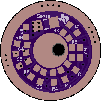
Here is the driver mostly populated:
!{width:50%}http://i.imgur.com/J7L4pil.png!:http://i.imgur.com/J7L4pil.png !{width:50%}http://i.imgur.com/BQpbCfJ.png!:http://i.imgur.com/BQpbCfJ.png
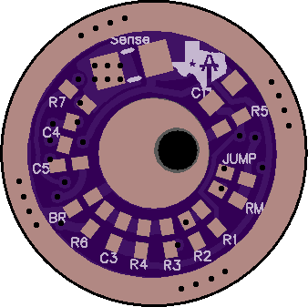
Here is the driver empty:
!{width:50%}http://i.imgur.com/azvkfwB.png!:http://i.imgur.com/azvkfwB.png !{width:50%}http://i.imgur.com/azvkfwB.png!:http://i.imgur.com/azvkfwB.png
Light saber 4 channel 25.4mm 7135 driver
by
2
layer board of
1.00x1.00
inches
(25.50x25.50
mm).
Shared on
February 19th, 2017 16:46.
This is a prototype 7135 based driver for a light saber. It supports 4 channels with a tiny25 MCU
The resistors are 0805 footprint, the diode is SOD323. The parts list is the same setup as the Texas Avenger driver series.
17mm V1 Texas Commander Tiny25
by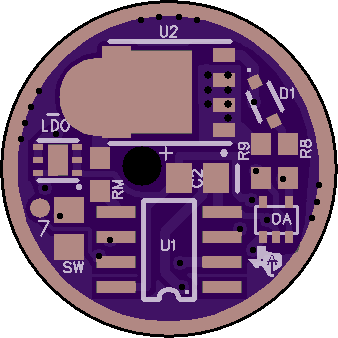
2
layer board of
0.68x0.68
inches
(17.15x17.15
mm).
Shared on
January 11th, 2017 15:41.
17mm LDO Texas Avenger Driver
by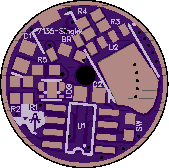
2
layer board of
0.68x0.68
inches
(17.15x17.15
mm).
Shared on
November 30th, 2016 16:17.
Info thread for this driver is here: http://budgetlightforum.com/node/48447
Ok, the idea with these drivers is that I can order them from OSHpark and keep them on hand for any build I may desire.
The real key feature is the 3 channels combined with bistro and Narsil firmware to give you nearly endless options when it comes to UI.
I find that the single 7135 is a great regulated low mode, even for high powered triples. Also a must for truly low moon modes.
The FET is obviously for turbo and works great at getting the most lumens possible.
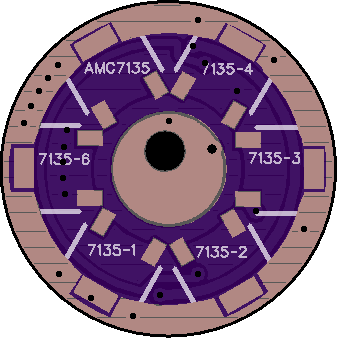
The bank of 6-8 7135’s is where things change from your normal FET+1 setup. This bank allows for a great non-PWM, regulated high mode on most lights and you can simply leave some 7135’s off to adjust it to your exact liking. Or if you need the space leave them all off and you can then clear any retaining ring you may desire.
Here is a feature list
- The latest FET + 7135 circuit that DEL scoped out and improved
- Full copper pour over the board to improve heatsinking of all the components
- 3 fully PWM channels, 1 to a LFPAK56 FET, 1 to a single 7135 on the top of the board and the last goes to a bank of 7135’s on the bottom of the board.
- Lots of edge clearance on the large drivers
- Large LED+ wire pass through, suitable for 20-18 gauge silicone wire, even larger if teflon coated wire.
- Bleeder resistor for lighted tailcaps
- Zener pads for higher voltage applications
- Attiny85 ready for all but the 17-19mm versions.
- Toykeepers amazing Bistro firmware : http://bazaar.launchpad.net/~toykeeper/flashlight-firmware/tiny25/files/head:/ToyKeeper/bistro/
- Thermal management with the bistro firmware!
So now to the Drivers themselves, they are designed around the parts list from DEL.
R1 : 22 k (or 220 k for e-switch lights, like you have been using) R2 : 4.7 k (or 47 k for e-switch lights) R3 : 100 k R4 : 47 ohm R5 : 4.7 ohm BR : 450-650ohm (optional, only for lighted tailcaps)
C1 : 10 uF C2 : 10 uF
Switch: pads for momentary e-switch
U1 : SOIC-8 for the Attiny85, the 13, 25 & 45 also fit on them U2 : LFPAK56 MOSFET (aka, “FET”). PSMN3R0-30YLDX is a popular cheap option, the SIR800DP is better but costs more.
LDO : designed around the LT3009EDC-5 or LT3009IDC-5
7135 : Standard 350ma or 380ma 7135’s can be installed on these pads. I prefer 350ma myself. You will need to clip the center pin of the top side 7135 if you plan to use a bleeder resistor. The 7135’s can be purchased from http://www.mtnelectronics.com/index.php?route=product/product&path=25_76&product_id=60 or https://www.fasttech.com/products/1124300
The resisters are all 0603 package (but you can use 0805 if you desire, just have to be more careful when building the driver).
Diode and Zener are both SOD-323 package.
The C1 cap is 0805 in all cases. C2 is 0603 in all cases (0805 could be used). The OTC is 0603 in the 17mm version and 0805 in the others, this is to make e-switch conversions easier.
You can fit 0805 on the 0603 pads if you are careful but if ordering new components, might as well go with 0603. The same can be done in reverse, you can put 0603 on the 0805 pads.
Here is a DigiKey shopping cart with the components I used, there are both better and also cheaper options available if you want to pick out your own, so this is just for reference I like getting a bit tighter tolerance OTC as it can help when things get hot for example).
The items with a quantity of 1 have multiple options that you will need to pick from in the cart. These are the FET’s and MCU. The SIR404 is the better FET but costs over twice the price, the NXP works just fine for most things. The other are the Attiny version that you want. As it stands right now you need the Attiny25 for Bistro and the Attiny85 for Narsil (aka, e-switch). You can also get the MCU/FET from RMM as well for a bit less money. http://www.mtnelectronics.com/index.php?route=product/category&path=25_104
http://www.digikey.com/short/3hzvd7
Also note that the cart includes both 0805 and 0603 OTC caps, you can remove one if you desire. The 7135’s are not included in this shopping cart as I don’t think digikey sells them, they are best ordered from links above.
The firmware that can be used with this driver is the Bistro Tripledown variation which can be found here: http://bazaar.launchpad.net/~toykeeper/flashlight-firmware/tiny25/files/head:/ToyKeeper/bistro/
https://s4.postimg.org/nyr04zj4t/bistro_ui.png
The downloads from OSHpark includes the source files for diptrace for anyone that wants to play around with it, along with pictures of the drivers assembled from diptrace to make assembly easier and a schematic for each one.
Here is the schematic that is used for all of them (save for the number of 7135’s of course).
http://i.imgur.com/0fDDPV4.jpg
46mm Q8 - SRK Texas Buck flashlight driver
by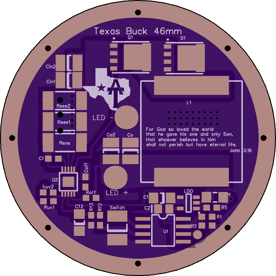
2
layer board of
1.82x1.82
inches
(46.15x46.15
mm).
Shared on
November 29th, 2016 23:17.
Here goes. Hopefully I didn’t mess anything up. Your risk, not mine. Only buy and build what YOU want. I have nothing to do with it. Smile
Parts list for 16.8V input, 12V nominal output, driving 4p xhp-35 at 2.5A per LED, 576 khz, 10A total (can go higher, but it’s an experimental driver)
The Parts
(see shopping list below if impatient)
MCU: Attiny85 the normal one, attiny85-20SUR I believe is usually fine. V version is also fine I think. (However if driving with 4.2V an attiny85V should probably be used because this driver presently requires an LDO for the mcu even for 1S batteries and the LDO will need to operate below the lowest battery level, needs more thought though and wil require some resistor value changes)
LDO: MIC5235 3.0V (other voltages CAN work, but require some resistor value changes)
Buck IC: LM3409 10-MSOP-PowerPad (or EP)
Inductor, must be 17.15*17.15mm or very close. 10uH absolute minimum inductance. 30mohm max resistance.
Vishay IHLP6767GZER150M11 is a good choice since resistance matters most. It’s very expensive though, $6!!, but other alternatives are about the same.
Diode, “8PowerTDFN” (might be compatible with similarly named footprints?) STPS30M60DJF-TR has a low 0.5V Vf and low leakage current when hot.
Mosfet:
Powerflat 5x6 p-channel FET (PFET), Infineon BSC084P03NS3 G Balances low Rdson with low gate capacitance. Gate charge divided by voltage should be less than ~12nF at worst. Half that is better. Rds on should probably be less than 20mOhm at worst. Low Rdson is good for high power. Low gate charge is good for low-current efficiency. It’s usually some tradeoff.
Caps:
C2 10.uF 0805, Vcc bypass 4V minimum, 6.3V or more highly preferred, 10%
Cf 1uF 0603, Gate drive bypass, 16V 10%
C1 10uF 1206 , LDO input bypass, 35V 10%
Cf2 10uF 1206, Iadj voltage filter, 4V minimum (6.3 preferred). 10%, x7r preferred but 125C rated should do. Alternative: 220uF for soft mode transitions. Tantalum and high ESR (ohms even) are OK here.
Cin 10uF 1206 or 1210, Input cap, 35V 10%, two minimum, 3 x 1206’s should fit. 4 might fit and is even better. <20% dissipation factor at 1Mhz, 10% prefered.
Co 10uF 1206 or 1210, Output cap, 35V 10% One is enough but two is insurance. <10% dissipation factor (5 is better), with good performance up to 1Mhz.
Just buy ten 1206 uF caps and you’re set. Cin and Co should be high quality caps.
Coff 470pf 0603 35V Buck off-time cap.
All caps should be ceramic unless stated, X7R or better strongly preferred (125C or higher rated) .
Resistors:
JMP 2010 0-ohm 1/10 W is fine.
R1 220k 0603 for e-switch 22k for clicky maybe. (with OTC mods now under development, the clicky issue will dissappear)
R2 12k 0603 for e-switch, 1.2k for clicky maybe.
R5 4.7 ohm 0603 1/8 to ¼ watt might be wise here, but 1/10 should be ok I think.
BR for lighted tailcap 470-630 ohm so I’ve read, optional.
Rf2 3.9K 0603
Rf3 2.7K 0603 (Could use 4.7k and 3.3k also for a little softer mode transitions with the 220uF cap)
Roff 4.7k 0603 with the 470pf Cf, this will give very roughly 580 khz, which seems ok.
Rsense, 2512, current sense resistors, X 3. 0.074 ohm each, 2W rated, adjusted for max current, see below.
Ruv2, any value, 0-ohm is even ok. 4.7k is also fine for example
Ruv1, leave off.
All resistors should be 1% tolerance, rated for high temperature, 155C preferred, 1/10 W or more unless specified
Adjustments
RSense
Max current occurs at 0.248V drop across Rsense.
So Rsense_total=0.248/Imax.
But there are three resistors, so if they are the same, they should each be:
Rses1=3*0.248/Imax. Err on the high side of resistance values to be safe.
But no software adjustment can ever make the current higher than the max value set here.
Ex: 2.5A for xph35*4= 10A total.
Rses= 3*0.248/10=0.074 , closest match, 0.075 ok.
Soft mode transitions:
To achieve slow (~0.33 s RC) you can use a Cf2 of 220uF and adjust speed by increasing or decreasing Rf2 and Rf3. Some options are:
Rf2: 3.9K, Rf3: 2.7K (flintrock’s favorite) ~0.35s RC time
Rf2 4.7K, Rf3 3.3K ~.43s RC time requires one less new value. Much larger and the current control circuit gets an offset, but it should be < 0.7% offset with these values still. Twice as high could still be ok but I think these RC values should feel nice. PWM will be used to get lowest modes anyway so a small control offset is ok.
These are chosen to prioritize resistors, but either matches the max control voltage to better than 1.2% after bias current correction. For best precision you can use a 1.02K and a 715ohm, but won’t get very soft mode transitions and probably won’t notice the precision improvement. If you’re using a 10uF cap anyway, then you can as well use these lower resistor values.
Expert tuning:
Roff:
In brief, increasing Roff decreases buck frequency, nearly proportionally, and of course decreasing Roff increases frequency. You can vary it by about twice in either direction. Higher frequency uses more switching power which is important for low power modes, however lower frequency has more ripple current which also impacts low power modes. For middle modes, low frequency is best. For lowest modes, it’s not clear yet (maybe never will be).
The frequency of the buck is determined by the offtime and the duty cycle. The duty cycle is approximately Vo/Vin. The off time is given by equation 4 in the manual:
http://www.ti.com/lit/ds/symlink/lm3409-q1.pdf (link is external)
or approximated by equation 6 (might as well use 4).
The frequency is (1-Vo/Vin)/t_off. As Vin gets very close to Vo this approaches 0 frequency, so as you near direct drive for low batteries or high current, the buck just stays on. For 16.8V in and 12 to 13V out, a good frequency target is probably around 500khz.
Iadj:
Rf2, Rf3, Cf2, LDO voltage, and a pwm duty cycle all determine the current set point. Only duty cycle should really need to be adjusted though (through software modes) for current control. Max current is adjusted with the sense resistor, not with this. Of course software could limit the duty cycle, but that’s not the safest approach to limiting current.
LM3409 low voltage shutoff
Ruv1, Ruv2 are the voltage divider for buck IC shutoff. This is redundant with MCU shutoff. You can leave off Ruv1 entirely and use pretty much any value at all for Ruv2 then. This will disable this feature.
If you want to use this feature, there are two concerns, the cuttoff value and the hysteresis. If the IC cuts off at 2.7V but the unloaded battery voltage recovers to 3.1V and the hysteresis is only 0.1V, it will immediately turn back on because the IC is still powered. There is no mechanism to interface this with software to lock out or lower the mode, so it will probably flicker on and off. Best is probably to have very large hysteresis. Presumably a power cycle will reset the hysteresis and mode programming that starts in low modes could allow the light to be turned back on at lower power, so the best solution is probably to use a large hysteresis. Hysteresisis in volts per cell h is:
h=.000011VRuv2
Then
Ruv1=1.24*Ruv2/(Voff-1.24)
So a 110k Ruv2 would give 1.2V/cell hysteresis, should be enough, and pairs well with a 33k Ruv1 for a 2.7V cuttoff, 36k for 2.5V, or 30k for 2.9V.
Shopping list
Digikey carts will apparently expire and they only work on digikey.
This is better:
References Quantity digikey Description
U1 1 ATTINY85-20SURCT-ND IC MCU 8BIT 8KB FLASH 8SOIC
LDO 1 576-2783-1-ND IC REG LDO 3V 0.15A SOT23-5
U2 1 LM3409MY/NOPBCT-ND IC LED DRIVER CTRLR DIM 10MSOP
L1 1 541-1287-1-ND FIXED IND 15UH 14A 14.4 MOHM SMD
D1 1 497-12421-1-ND DIODE SCHOTTKY 60V 30A POWERFLAT
Q1 1 BSC084P03NS3 GCT-ND MOSFET P-CH 30V 14.9A TDSON-8
C2 10 1276-2872-1-ND CAP CER 10UF 16V X7R 0805
Cf 1 311-1446-1-ND CAP CER 1UF 16V X7R 0603
Cf2,Cin,Co,C1 10 1276-6767-1-ND CAP CER 10UF 50V X7R 1206
Cf2 alternate 1 490-13970-1-ND CAP CER 220UF 6.3V X5R 1206
Coff 10 1276-1094-1-ND CAP CER 470PF 50V X7R 0603
JMP 1 YAG3380CT-ND RES SMD 0.0 OHM JUMPER 3/4W 2010
R1 10 311-220KHRCT-ND RES SMD 220K OHM 1% 1/10W 0603
R2 10 311-12.0KHRCT-ND RES SMD 12K OHM 1% 1/10W 0603
Roff, Ruv1 10 311-4.70KHRCT-ND RES SMD 4.7K OHM 1% 1/10W 0603
R5 10 RNCP0603FTD4R70CT-ND RES SMD 4.7 OHM 1% 1/8W 060
Rf2 10 311-3.90KHRCT-ND RES SMD 3.9K OHM 1% 1/10W 0603
Rf3 10 311-2.70KHRCT-ND RES SMD 2.7K OHM 1% 1/10W 0603
Rsns 3 696-1670-1-ND RES SMD 0.075 OHM 1% 2W 2512
The 10 uf 1206 Ci Co caps keep going on backorder. That’s because they are cheap and seem to be really nice caps.
These are an alternative, at twice the price, and slightly worse ESR, but still good and maybe available much faster: 1276-3103-1-ND, or 1276-3102-1-ND
USING THE SHOPPING LIST:
You can install
https://1clickbom.com/ (link is external) in firefox (doesn’t work as well in chrome)
And cut the table above and hit paste in the browser tool, and “complete” (hit complete several times actually, waiting for it to update between each, seems to help) to get shopping carts at all digikey, mouser, Newark, Farnell, (no arrow :() .. Click the add to cart icon on each to automatically create a shopping cart on any of them. Click “copy” and you get a table with part numbers from all of them. It’s pretty neat actually. Of course a few parts are missing at mouser etc because these were chosen at digikey.
Anyone clever might let this simmer a couple of days. TA please give it a good looking over. Also anyone else with expertise on the MCU side.
Updates, changed C2 to 10uf and now 0805, as needed for LDO. Chanted R1 and R2 to work with 1.1V reference as now standard in bistro.