OSH Park
46mm Q8 - SRK Texas Buck flashlight driver
- You need to sign in or sign up before continuing.
46mm Q8 - SRK Texas Buck flashlight driver
by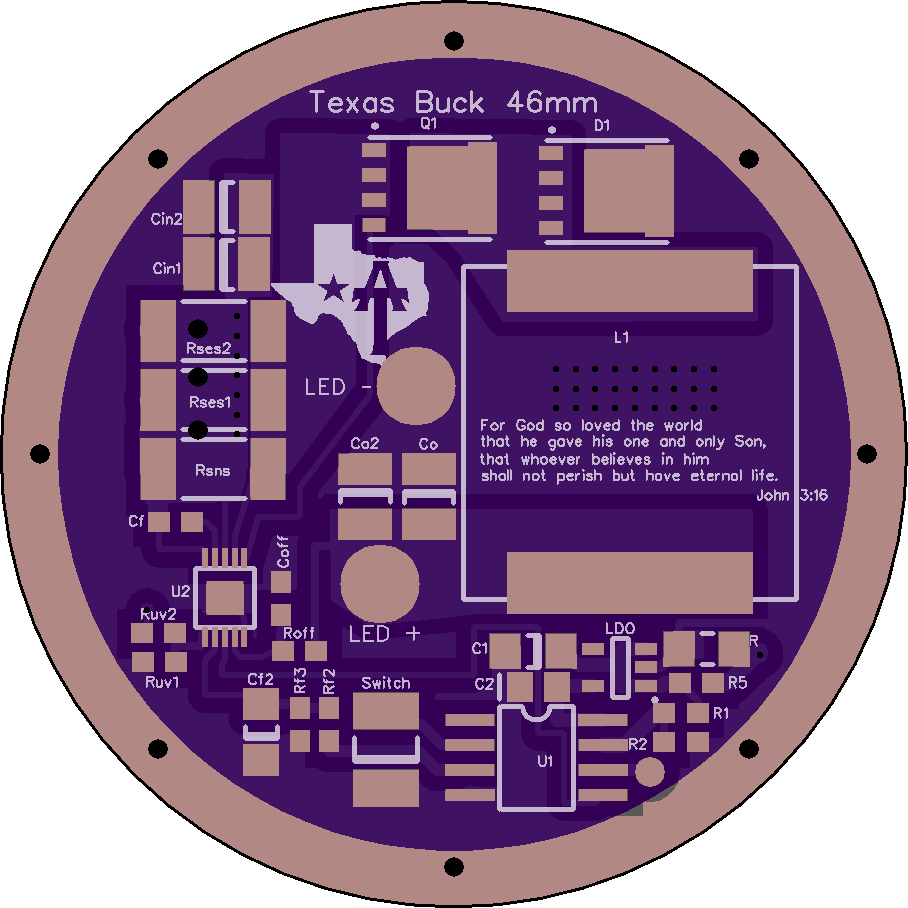
2
layer board of
1.82x1.82
inches
(46.15x46.15
mm).
Shared on
November 29th, 2016 23:17.
Here goes. Hopefully I didn’t mess anything up. Your risk, not mine. Only buy and build what YOU want. I have nothing to do with it. Smile
Parts list for 16.8V input, 12V nominal output, driving 4p xhp-35 at 2.5A per LED, 576 khz, 10A total (can go higher, but it’s an experimental driver)
The Parts
(see shopping list below if impatient)
MCU: Attiny85 the normal one, attiny85-20SUR I believe is usually fine. V version is also fine I think. (However if driving with 4.2V an attiny85V should probably be used because this driver presently requires an LDO for the mcu even for 1S batteries and the LDO will need to operate below the lowest battery level, needs more thought though and wil require some resistor value changes)
LDO: MIC5235 3.0V (other voltages CAN work, but require some resistor value changes)
Buck IC: LM3409 10-MSOP-PowerPad (or EP)
Inductor, must be 17.15*17.15mm or very close. 10uH absolute minimum inductance. 30mohm max resistance.
Vishay IHLP6767GZER150M11 is a good choice since resistance matters most. It’s very expensive though, $6!!, but other alternatives are about the same.
Diode, “8PowerTDFN” (might be compatible with similarly named footprints?) STPS30M60DJF-TR has a low 0.5V Vf and low leakage current when hot.
Mosfet:
Powerflat 5x6 p-channel FET (PFET), Infineon BSC084P03NS3 G Balances low Rdson with low gate capacitance. Gate charge divided by voltage should be less than ~12nF at worst. Half that is better. Rds on should probably be less than 20mOhm at worst. Low Rdson is good for high power. Low gate charge is good for low-current efficiency. It’s usually some tradeoff.
Caps:
C2 10.uF 0805, Vcc bypass 4V minimum, 6.3V or more highly preferred, 10%
Cf 1uF 0603, Gate drive bypass, 16V 10%
C1 10uF 1206 , LDO input bypass, 35V 10%
Cf2 10uF 1206, Iadj voltage filter, 4V minimum (6.3 preferred). 10%, x7r preferred but 125C rated should do. Alternative: 220uF for soft mode transitions. Tantalum and high ESR (ohms even) are OK here.
Cin 10uF 1206 or 1210, Input cap, 35V 10%, two minimum, 3 x 1206’s should fit. 4 might fit and is even better. <20% dissipation factor at 1Mhz, 10% prefered.
Co 10uF 1206 or 1210, Output cap, 35V 10% One is enough but two is insurance. <10% dissipation factor (5 is better), with good performance up to 1Mhz.
Just buy ten 1206 uF caps and you’re set. Cin and Co should be high quality caps.
Coff 470pf 0603 35V Buck off-time cap.
All caps should be ceramic unless stated, X7R or better strongly preferred (125C or higher rated) .
Resistors:
JMP 2010 0-ohm 1/10 W is fine.
R1 220k 0603 for e-switch 22k for clicky maybe. (with OTC mods now under development, the clicky issue will dissappear)
R2 12k 0603 for e-switch, 1.2k for clicky maybe.
R5 4.7 ohm 0603 1/8 to ¼ watt might be wise here, but 1/10 should be ok I think.
BR for lighted tailcap 470-630 ohm so I’ve read, optional.
Rf2 3.9K 0603
Rf3 2.7K 0603 (Could use 4.7k and 3.3k also for a little softer mode transitions with the 220uF cap)
Roff 4.7k 0603 with the 470pf Cf, this will give very roughly 580 khz, which seems ok.
Rsense, 2512, current sense resistors, X 3. 0.074 ohm each, 2W rated, adjusted for max current, see below.
Ruv2, any value, 0-ohm is even ok. 4.7k is also fine for example
Ruv1, leave off.
All resistors should be 1% tolerance, rated for high temperature, 155C preferred, 1/10 W or more unless specified
Adjustments
RSense
Max current occurs at 0.248V drop across Rsense.
So Rsense_total=0.248/Imax.
But there are three resistors, so if they are the same, they should each be:
Rses1=3*0.248/Imax. Err on the high side of resistance values to be safe.
But no software adjustment can ever make the current higher than the max value set here.
Ex: 2.5A for xph35*4= 10A total.
Rses= 3*0.248/10=0.074 , closest match, 0.075 ok.
Soft mode transitions:
To achieve slow (~0.33 s RC) you can use a Cf2 of 220uF and adjust speed by increasing or decreasing Rf2 and Rf3. Some options are:
Rf2: 3.9K, Rf3: 2.7K (flintrock’s favorite) ~0.35s RC time
Rf2 4.7K, Rf3 3.3K ~.43s RC time requires one less new value. Much larger and the current control circuit gets an offset, but it should be < 0.7% offset with these values still. Twice as high could still be ok but I think these RC values should feel nice. PWM will be used to get lowest modes anyway so a small control offset is ok.
These are chosen to prioritize resistors, but either matches the max control voltage to better than 1.2% after bias current correction. For best precision you can use a 1.02K and a 715ohm, but won’t get very soft mode transitions and probably won’t notice the precision improvement. If you’re using a 10uF cap anyway, then you can as well use these lower resistor values.
Expert tuning:
Roff:
In brief, increasing Roff decreases buck frequency, nearly proportionally, and of course decreasing Roff increases frequency. You can vary it by about twice in either direction. Higher frequency uses more switching power which is important for low power modes, however lower frequency has more ripple current which also impacts low power modes. For middle modes, low frequency is best. For lowest modes, it’s not clear yet (maybe never will be).
The frequency of the buck is determined by the offtime and the duty cycle. The duty cycle is approximately Vo/Vin. The off time is given by equation 4 in the manual:
http://www.ti.com/lit/ds/symlink/lm3409-q1.pdf (link is external)
or approximated by equation 6 (might as well use 4).
The frequency is (1-Vo/Vin)/t_off. As Vin gets very close to Vo this approaches 0 frequency, so as you near direct drive for low batteries or high current, the buck just stays on. For 16.8V in and 12 to 13V out, a good frequency target is probably around 500khz.
Iadj:
Rf2, Rf3, Cf2, LDO voltage, and a pwm duty cycle all determine the current set point. Only duty cycle should really need to be adjusted though (through software modes) for current control. Max current is adjusted with the sense resistor, not with this. Of course software could limit the duty cycle, but that’s not the safest approach to limiting current.
LM3409 low voltage shutoff
Ruv1, Ruv2 are the voltage divider for buck IC shutoff. This is redundant with MCU shutoff. You can leave off Ruv1 entirely and use pretty much any value at all for Ruv2 then. This will disable this feature.
If you want to use this feature, there are two concerns, the cuttoff value and the hysteresis. If the IC cuts off at 2.7V but the unloaded battery voltage recovers to 3.1V and the hysteresis is only 0.1V, it will immediately turn back on because the IC is still powered. There is no mechanism to interface this with software to lock out or lower the mode, so it will probably flicker on and off. Best is probably to have very large hysteresis. Presumably a power cycle will reset the hysteresis and mode programming that starts in low modes could allow the light to be turned back on at lower power, so the best solution is probably to use a large hysteresis. Hysteresisis in volts per cell h is:
h=.000011VRuv2
Then
Ruv1=1.24*Ruv2/(Voff-1.24)
So a 110k Ruv2 would give 1.2V/cell hysteresis, should be enough, and pairs well with a 33k Ruv1 for a 2.7V cuttoff, 36k for 2.5V, or 30k for 2.9V.
Shopping list
Digikey carts will apparently expire and they only work on digikey.
This is better:
References Quantity digikey Description
U1 1 ATTINY85-20SURCT-ND IC MCU 8BIT 8KB FLASH 8SOIC
LDO 1 576-2783-1-ND IC REG LDO 3V 0.15A SOT23-5
U2 1 LM3409MY/NOPBCT-ND IC LED DRIVER CTRLR DIM 10MSOP
L1 1 541-1287-1-ND FIXED IND 15UH 14A 14.4 MOHM SMD
D1 1 497-12421-1-ND DIODE SCHOTTKY 60V 30A POWERFLAT
Q1 1 BSC084P03NS3 GCT-ND MOSFET P-CH 30V 14.9A TDSON-8
C2 10 1276-2872-1-ND CAP CER 10UF 16V X7R 0805
Cf 1 311-1446-1-ND CAP CER 1UF 16V X7R 0603
Cf2,Cin,Co,C1 10 1276-6767-1-ND CAP CER 10UF 50V X7R 1206
Cf2 alternate 1 490-13970-1-ND CAP CER 220UF 6.3V X5R 1206
Coff 10 1276-1094-1-ND CAP CER 470PF 50V X7R 0603
JMP 1 YAG3380CT-ND RES SMD 0.0 OHM JUMPER 3/4W 2010
R1 10 311-220KHRCT-ND RES SMD 220K OHM 1% 1/10W 0603
R2 10 311-12.0KHRCT-ND RES SMD 12K OHM 1% 1/10W 0603
Roff, Ruv1 10 311-4.70KHRCT-ND RES SMD 4.7K OHM 1% 1/10W 0603
R5 10 RNCP0603FTD4R70CT-ND RES SMD 4.7 OHM 1% 1/8W 060
Rf2 10 311-3.90KHRCT-ND RES SMD 3.9K OHM 1% 1/10W 0603
Rf3 10 311-2.70KHRCT-ND RES SMD 2.7K OHM 1% 1/10W 0603
Rsns 3 696-1670-1-ND RES SMD 0.075 OHM 1% 2W 2512
The 10 uf 1206 Ci Co caps keep going on backorder. That’s because they are cheap and seem to be really nice caps.
These are an alternative, at twice the price, and slightly worse ESR, but still good and maybe available much faster: 1276-3103-1-ND, or 1276-3102-1-ND
USING THE SHOPPING LIST:
You can install
https://1clickbom.com/ (link is external) in firefox (doesn’t work as well in chrome)
And cut the table above and hit paste in the browser tool, and “complete” (hit complete several times actually, waiting for it to update between each, seems to help) to get shopping carts at all digikey, mouser, Newark, Farnell, (no arrow :() .. Click the add to cart icon on each to automatically create a shopping cart on any of them. Click “copy” and you get a table with part numbers from all of them. It’s pretty neat actually. Of course a few parts are missing at mouser etc because these were chosen at digikey.
Anyone clever might let this simmer a couple of days. TA please give it a good looking over. Also anyone else with expertise on the MCU side.
Updates, changed C2 to 10uf and now 0805, as needed for LDO. Chanted R1 and R2 to work with 1.1V reference as now standard in bistro.