
OSH Park
Profile for Zarradeth
- You need to sign in or sign up before continuing.
Shared projects
JVS JAMMA I/O Adapter
by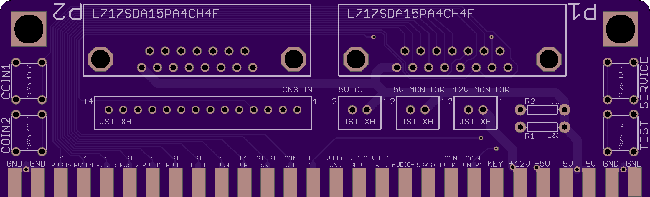
2
layer board of
4.41x1.34
inches
(112.01x34.01
mm).
Shared on
April 3rd, 2017 06:49.
(v1.2)
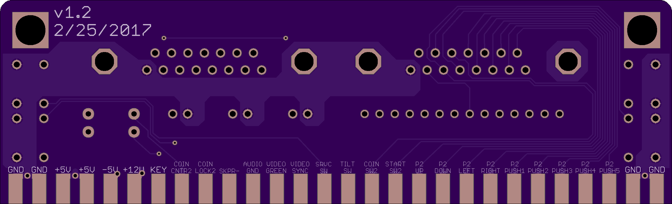
An adapter board for hooking up joysticks to a JVS I/O Board that uses JAMMA, specifically designed with the Sega 838-13683-93 REV. B in mind. This board is not designed to power the I/O, the I/O should be receiving power from another source (such as the CN6 header on the REV B). This design also assumes that your I/O board will provide +5v/+12v on the JAMMA connector (but it will be mostly functional without it).
Buttons 1-5 are on the JAMMA edge, button 6 is connected up to the 14 pin connector which is meant to be hooked up to CN3 on the REV B. Technically only pins 4 (P1 Button 6) and 8 (P2 Button 6) need to be hooked up on the 14 pin connector. All pins besides those 2 on the connector are NC. So, again, the only pins you would need to wire are 4 and 8 (which aren’t even needed if you don’t care about 6 button support).
The board has plugs for a +5v and +12v monitor, they are not required. There is also a 2nd plug for a +5v out, intended for use with a modified USB cable to power a Pi. These outputs will only work if the board is receiving power from the I/O board over the JAMMA edge (which is the case if the REV B is powered via CN6). On the 2 pin connectors Pin 1 is output and Pin 2 is ground. Theoretically you could possibly use these plugs as power input (as they connect to the JAMMA edge) to power the I/O, but the board was not designed for this.
The two resistors are connected between +5v and the coin meter pins on the JAMMA edge to spoof the existence of coin meters for games that require it. This will not work if the board is not receiving +5v from the JAMMA edge. The push buttons on the board are provided for ease of access to test/service/coin inputs, they do not need to be populated.
The board was designed to fit the following parts:
- All plugs are 2.5mm pitch, designed for JST XH plugs.
- The DB-15 connectors were designed for Amphenol’s L717SDA15PA4CH4F
- The push buttons were designed for TE Connectivity’s ALCOSWITCH Switches (1825910-6)
- The JAMMA edge was designed for a Suzo Happ female edge connector (with solder terminals), but should fit pretty much any JAMMA female connector. (Note: This board was designed for soldering a female connector onto the board, not for a female-female connector, the pins on the JAMMA edge on this board might be a bit too short to use a female-female connector, but it might work. It will for sure not work if your connector requires a slot for the Key, as this board has a pin (unused) in its place).
The DB-15 plugs use the wiring that should be found on most Superguns: http://www.thesupergun.com/electrical/standard-supergun-controller-wiring-diagram/
In case the site cannot be reached the wiring is as follows:
- GND
- Button 6
- Coin
- Button 4
- Button 2
- Right
- Down
- +5v*
- NC
- Button 5
- Start
- Button 3
- Button 1
- Left
- Up
*As with the other outputs on the board, pin 8 will only be outputting +5v if this board is receiving power from the I/O board over JAMMA. The board will still function if it is not receiving power, but none of the outputs will work (whether or not your controller will work without the +5v on pin 8 depends on how it’s wired. Standard Neo Geo/Supergun controllers should function without it).
NEOGEO Joystick Board (5mm)
by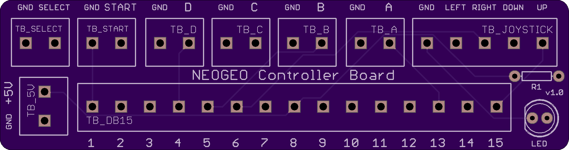
2
layer board of
3.88x1.02
inches
(98.50x26.01
mm).
Shared on
January 16th, 2017 06:53.
A board designed to help make building a joystick for a Neo Geo easy and clean. This design uses terminal blocks with a 5mm pitch.
The design has screw terminals for each line from the DB15 connector as well as terminals for each button and the joystick. There is also space for an LED (powered by the +5v from the Neo Geo) and an extra terminal for the +5v line in case you want to do something with that.
The board is designed for use with Phoenix Contact’s Combicon PT series 5mm terminal blocks (however others with the same pitch will most likely fit). There are 6 2 position blocks for the buttons (+1 extra if you want one for +5v). There is 1 5 position terminal block for the joystick and 1 15 position terminal block for the DB15 in from the system. You could use the board just fine without populating the terminals (soldering directly to the holes for the terminals) but if that’s your goal a nicer and smaller board could be made with just pads/holes.
Note: The LED (including its resistor R1) and the +5v terminal block are completely optional.
NEOGEO Joystick Board (3.5mm)
by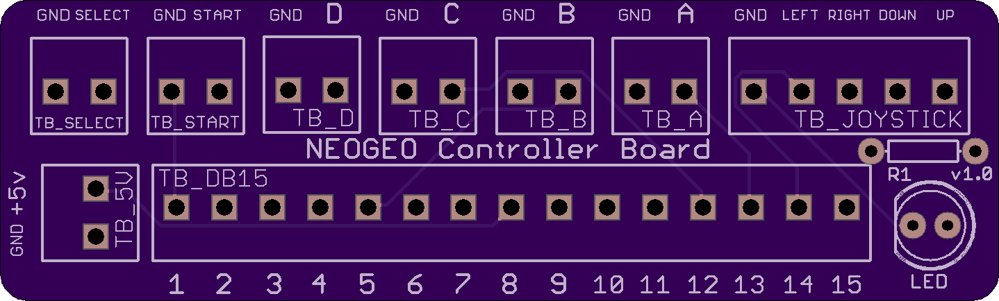
2
layer board of
2.88x0.87
inches
(73.02x22.02
mm).
Shared on
January 16th, 2017 06:53.
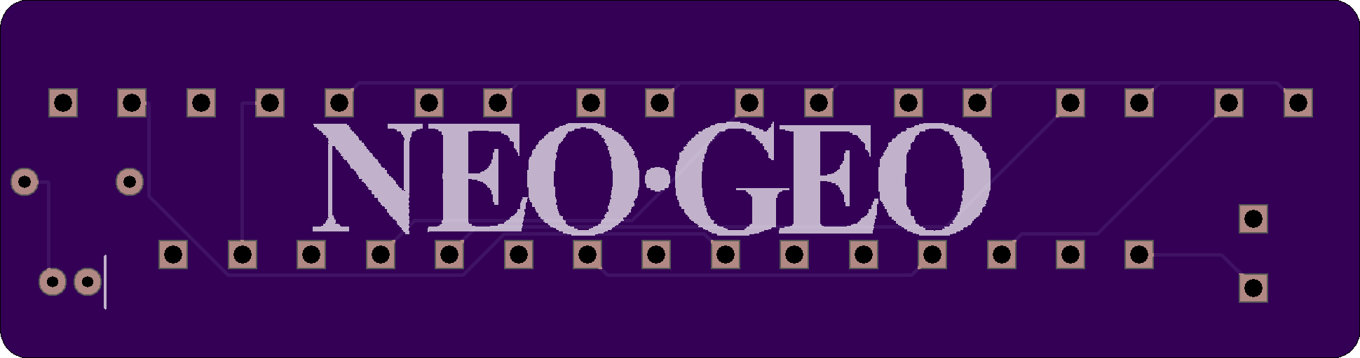
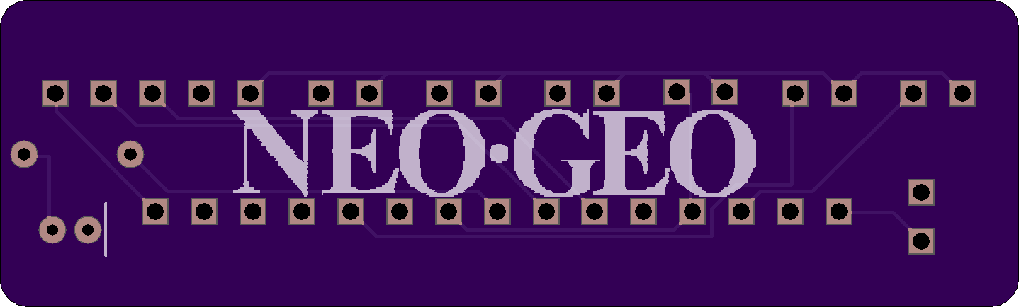
A board designed to help make building a joystick for a Neo Geo easy and clean. This design uses terminal blocks with a 3.5mm pitch.
The design has screw terminals for each line from the DB15 connector as well as terminals for each button and the joystick. There is also space for an LED (powered by the +5v from the Neo Geo) and an extra terminal for the +5v line in case you want to do something with that.
The board is designed for use with Phoenix Contact’s Combicon PT series 3.5mm terminal blocks (however others with the same pitch will most likely fit). There are 6 2 position blocks for the buttons (+1 extra if you want one for +5v). There is 1 5 position terminal block for the joystick and 1 15 position terminal block for the DB15 in from the system. You could use the board just fine without populating the terminals (soldering directly to the holes for the terminals) but if that’s your goal a nicer and smaller board could be made with just pads/holes.
Note: The LED (including its resistor R1) and the +5v terminal block are completely optional.
USB Line Voltage Inducer
by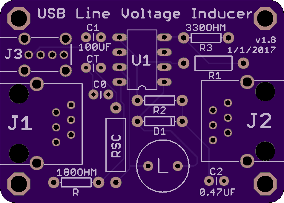
2
layer board of
1.90x1.36
inches
(48.29x34.54
mm).
Shared on
January 16th, 2017 06:53.
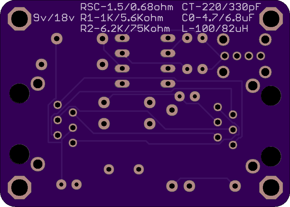
(v1.8)
A board for building a line voltage inducer (as part of a phone cable) powered by USB. Meant for use with a Dreamcast and DreamPi. The board includes a DC-DC boost converter which boosts the 5v supplied via the USB to the required voltage- both 9v and 18v are supported, you just have to populate the board for the appropriate voltage. Phone jacks are used instead of splicing the cable to make the inducer as easy to use as possible.
Line Voltage Inducer
by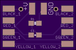
2
layer board of
0.65x0.43
inches
(16.46x10.80
mm).
Shared on
September 26th, 2016 08:27.
A board for building a line voltage inducer (as part of a phone cable). Meant for use with a Dreamcast and DreamPi. The capacitor (C1) and resistor (R1) are sized for a 0603 package.