
OSH Park
Profile for bwshockley
Shared projects
Mini SAM 2017-01-015
by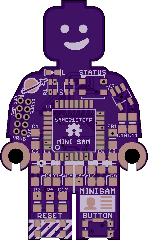

4
layer board of
0.95x1.55
inches
(24.21x39.32
mm).
Shared on
February 24th, 2017 15:47.
*Note this version updates version 2017/001-015 with a fix for the I2C disconnect jumper.
This is a LEGO Minifigure sized development board using an Atmel SAMD21E 32-Bit ARM chip. I basically followed the recommended layout/setup from the SAMD21 spec sheets.
Included on Mini SAM is a WS2812B LED pad connected to PIN 27, a 0603 LED connected to PIN 15, a reset button with support components per the datasheet, and a generic button that is active HIGH on PIN 28. The 0603 LED is connected in series with a 1Kohm resistor, part of R1, and care should be taken when selecting an 0603 LED such that at a supply of 3.3V, no more than 5mA is required.
Programming port is a standard10-pin SWD for ARM based processors, which is a 2x5 1.27mm pitch connector. The SWD line is pulled up with a 1Kohm resistor, part of R1. In the BOM, either purchase the 2x5 straight pin connector OR the 2x5 POGO connector and do not populate board.
The SDA/SCL pins are pulled high with 4.7KOhm resistors, R2, per SDA/SCL recommendations.
The voltage regulator is an AP2112K-3.3V which is rated at 600mA at 3.3V. Plenty of current for the SAMD21E and a few other accessories such as the WS2812B.
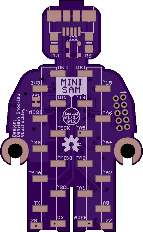
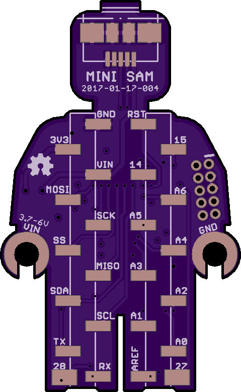
This version has SMT layout for two single row 2.54mm pitch headers on the back. It is designed to be protoboard friendly and when populated the headers are the same width as a DIL package (7.62mm or .3") and span the center of a protoboard.
PINs 27 and 28 are not connected to headers - due to lack of space - but instead have two pads near the bottom of the board. PIN 27 is connected to the on-board WS2812B. PIN 28 is connected to the on-board BUTTON.
The Analog Reference (PIN AREF) - has a pair of decoupling/filtering capacitors.
The micro-USB connector has an RC filter between the case/shield of the connector and GND. If R6 and C13 are left un-populated the case/shield is an open circuit - which is the next best option. Also included is space for a PRTR5V0U2X ESD protection circuit on USB Data lines. This may also be left un-populated and USB will function normally.
I have put together a sample BOM via Mouser.com which I’m including here. It can be used as a reference. Optional, but highly recommended components: SW2812B 3535 LED, 0603 LED, SW2 (BUTTON), R4, R5, R6, C13, and PRTR5V0U2X. R1 is for the 0603 LED and SWCLK - If not populating the 0603 LED this may be left un-populated as well and programming via SWD should still work as I’ve seen other boards without the 1Kohm resistor on SWCLK. R2 is the 4.7Kohm pull-up resistor pair for SDA/SCL. Many breakout boards using chips that run off SDA/SCL typically come with the 4.7Kohm pull-up resistor pair included - as such it may not be needed on Mini SAM - but it is included for ease of future components. Please review the schematic for additional details and be aware that the BOM on Mouser.com may be out of date. The SW2812B is not in the Mouser BOM - due to lack of parts.
I would suggest not purchasing the 2.54mm pitch SMT male headers from Mouser, as you can find this much cheaper elsewhere. The best I could find on Mouser is (2) 5-Pin and (2) 6-Pin headers. Mini SAM requires (2) 11-PIN headers. I suggest buying breakaway headers in 25-50 PIN lengths.
Arduino FIRMWARE/BOOTLOADER is complete, but I’m still testing all functions. So far all PINs work in digital setup and all analog PINs work accordingly. ANALOG and special function pins (MOSI, SDA, SCK, etc) can be accessed in Arduino by their name.
Please check my Github for the latest design files and bootloade/firmware.
More details can be found on Github
MINI_SAM_2017-01-012.brd
by
4
layer board of
0.95x1.55
inches
(24.21x39.32
mm).
Shared on
February 20th, 2017 22:27.
NOTE There is a error with the I2C pull-up disconnect in version 012 of the board. Please use version 015, which is also shared.**
This is a LEGO Minifigure sized development board using an Atmel SAMD21E 32-Bit ARM chip. I basically followed the recommended layout/setup from the SAMD21 spec sheets.
Included on Mini SAM is a WS2812B LED pad connected to PIN 27, a 0603 LED connected to PIN 15, a reset button with support components per the datasheet, and a generic button that is active HIGH on PIN 28. The 0603 LED is connected in series with a 1Kohm resistor, part of R1, and care should be taken when selecting an 0603 LED such that at a supply of 3.3V, no more than 5mA is required.
Programming port is a standard10-pin SWD for ARM based processors, which is a 2x5 1.27mm pitch connector. The SWD line is pulled up with a 1Kohm resistor, part of R1. In the BOM, either purchase the 2x5 straight pin connector OR the 2x5 POGO connector and do not populate board.
The SDA/SCL pins are pulled high with 4.7KOhm resistors, R2, per SDA/SCL recommendations.
The voltage regulator is an AP2112K-3.3V which is rated at 600mA at 3.3V. Plenty of current for the SAMD21E and a few other accessories such as the WS2812B.
This version has SMT layout for two single row 2.54mm pitch headers on the back. It is designed to be protoboard friendly and when populated the headers are the same width as a DIL package (7.62mm or .3") and span the center of a protoboard.
PINs 27 and 28 are not connected to headers - due to lack of space - but instead have two pads near the bottom of the board. PIN 27 is connected to the on-board WS2812B. PIN 28 is connected to the on-board BUTTON.
The Analog Reference (PIN AREF) - has a pair of decoupling/filtering capacitors.
The micro-USB connector has an RC filter between the case/shield of the connector and GND. If R6 and C13 are left un-populated the case/shield is an open circuit - which is the next best option. Also included is space for a PRTR5V0U2X ESD protection circuit on USB Data lines. This may also be left un-populated and USB will function normally.
I have put together a sample BOM via Mouser.com which I’m including here. It can be used as a reference. Optional, but highly recommended components: SW2812B 3535 LED, 0603 LED, SW2 (BUTTON), R4, R5, R6, C13, and PRTR5V0U2X. R1 is for the 0603 LED and SWCLK - If not populating the 0603 LED this may be left un-populated as well and programming via SWD should still work as I’ve seen other boards without the 1Kohm resistor on SWCLK. R2 is the 4.7Kohm pull-up resistor pair for SDA/SCL. Many breakout boards using chips that run off SDA/SCL typically come with the 4.7Kohm pull-up resistor pair included - as such it may not be needed on Mini SAM - but it is included for ease of future components. Please review the schematic for additional details and be aware that the BOM on Mouser.com may be out of date. The SW2812B is not in the Mouser BOM - due to lack of parts.
I would suggest not purchasing the 2.54mm pitch SMT male headers from Mouser, as you can find this much cheaper elsewhere. The best I could find on Mouser is (2) 5-Pin and (2) 6-Pin headers. Mini SAM requires (2) 11-PIN headers. I suggest buying breakaway headers in 25-50 PIN lengths.
Arduino FIRMWARE/BOOTLOADER is complete, but I’m still testing all functions. So far all PINs work in digital setup and all analog PINs work accordingly. ANALOG and special function pins (MOSI, SDA, SCK, etc) can be accessed in Arduino by their name.
Please check my Github for the latest design files and bootloade/firmware.
More details can be found on Github
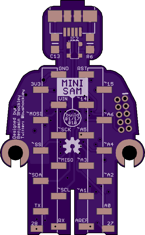
MINI SAM 2017/01-010
by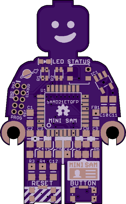
4
layer board of
0.95x1.55
inches
(24.21x39.32
mm).
Shared on
February 3rd, 2017 21:29.
This is a LEGO Minifigure sized development board using an Atmel SAMD21E 32-Bit ARM chip. I basically followed the recommended layout/setup from the SAMD21 spec sheets.
Included on Mini SAM is a WS2812B LED pad connected to PIN 27, a 0603 LED connected to PIN 15, a reset button with support components per the datasheet, and a generic button that is active HIGH on PIN 28. The 0603 LED is connected in series with a 1Kohm resistor, part of R1, and care should be taken when selecting an 0603 LED such that at a supply of 3.3V, no more than 5mA is required.
Programming port is a standard10-pin SWD for ARM based processors, which is a 2x5 1.27mm pitch connector. The SWD line is pulled up with a 1Kohm resistor, part of R1. In the BOM, either purchase the 2x5 straight pin connector OR the 2x5 POGO connector and do not populate board.
The SDA/SCL pins are pulled high with 4.7KOhm resistors, R2, per SDA/SCL recommendations.
The voltage regulator is an AP2112K-3.3V which is rated at 600mA at 3.3V. Plenty of current for the SAMD21E and a few other accessories such as the WS2812B.
This version has SMT layout for two single row 2.54mm pitch headers on the back. It is designed to be protoboard friendly and when populated the headers are the same width as a DIL package (7.62mm or .3") and span the center of a protoboard.
PINs 27 and 28 are not connected to headers - due to lack of space - but instead have two pads near the bottom of the board. PIN 27 is connected to the on-board WS2812B. PIN 28 is connected to the on-board BUTTON.
The Analog Reference (PIN AREF) - has a pair of decoupling/filtering capacitors.
The micro-USB connector has an RC filter between the case/shield of the connector and GND. If R6 and C13 are left un-populated the case/shield is an open circuit - which is the next best option. Also included is space for a PRTR5V0U2X ESD protection circuit on USB Data lines. This may also be left un-populated and USB will function normally.
I have put together a sample BOM via Mouser.com which I’m including here. It can be used as a reference. Optional, but highly recommended components: SW2812B 3535 LED, 0603 LED, SW2 (BUTTON), R4, R5, R6, C13, and PRTR5V0U2X. R1 is for the 0603 LED and SWCLK - If not populating the 0603 LED this may be left un-populated as well and programming via SWD should still work as I’ve seen other boards without the 1Kohm resistor on SWCLK. R2 is the 4.7Kohm pull-up resistor pair for SDA/SCL. Many breakout boards using chips that run off SDA/SCL typically come with the 4.7Kohm pull-up resistor pair included - as such it may not be needed on Mini SAM - but it is included for ease of future components. Please review the schematic for additional details and be aware that the BOM on Mouser.com may be out of date. The SW2812B is not in the Mouser BOM - due to lack of parts.
I would suggest not purchasing the 2.54mm pitch SMT male headers from Mouser, as you can find this much cheaper elsewhere. The best I could find on Mouser is (2) 5-Pin and (2) 6-Pin headers. Mini SAM requires (2) 11-PIN headers. I suggest buying breakaway headers in 25-50 PIN lengths.
Arduino FIRMWARE/BOOTLOADER is complete, but I’m still testing all functions. So far all PINs work in digital setup and all analog PINs work accordingly. ANALOG and special function pins (MOSI, SDA, SCK, etc) can be accessed in Arduino by their name.
Please check my Github for the latest design files and bootloade/firmware.
More details can be found on Github
Mini SAM - Protoboard - TQFP - 2017-01-17-004
by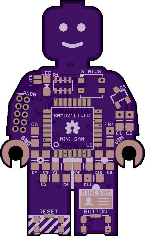
4
layer board of
0.96x1.55
inches
(24.36x39.47
mm).
Shared on
January 20th, 2017 18:32.
This is a LEGO Minifigure sized development board using an Atmel SAMD21E 32-Bit ARM chip. I basically followed the recommended layout/setup from the SAMD21 spec sheets.
Included on Mini SAM is a WS2812B LED pad connected to PIN 28, which is shared with a standard 0603 LED as well. The user may decide which item to populate or may populate both and use the jumper to enable/disable the 0805 LED. Keep in mind the 0805 LED/1.5KOhm Resistor combo MUST draw less than 7mA - as it is connected directly to the SAMD21E.
Programming port is a basic SWD for ARM based processors, which is a 2x5 1.27mm pitch connector. The SWD line is pulled up with a 1.5Kohm resistor.
The SDA/SCL pins are pulled up with 1.5KOhm resistors.
Voltage regulator is MCP1700 which is rated at 250mA at 3.3V. Plenty of current for the SAMD21E and a few other accessories such as the WS2812B.
This version has SMT layout for single row 2.54mm pitch headers on the back. It is designed to be protoboard friendly and when populated the headers are the same width as a DIL package (7.62mm or .3").
PINs 27 and 28 are not connected to headers - due to lack of space. PIN 27 is used for the on-board LED or WS2812B. PIN 28 is connected to the on-board BUTTON, but both PINs have solder pads on the back of the board for additional flexibility.
I have put together a sample BOM via Mouser.com which I’m including here. It can be used as a reference. Items that do not need to be populated to work: SW2812B 3535 LED, 0603 LED, SW2 (BUTTON). The SW2812B is not in the Mouser BOM - due to lack of parts. I would suggest not purchasing the 2.54mm pitch SMT male headers from Mouser, as you can find this much cheaper elsewhere. Mini SAM requires (2) 11-PIN headers. I suggest buying breakaway headers in 25-50 PIN lengths.
*NOTE - I made a change to the BOM and included two dual resistor 0606 arrays instead of a single 1.5KOhm 1206 quad array. The dual resistor arrays include 1KOhm and 4.7KOhm. You may use the same footprint on this board, be sure to place the 4.7KOhm array on the side closest to the WS2812B (for the SDA/SCL lines) and the 1KOhm on the left side closest to the 0805 LED. The 1.5K quad should also work, but I prefer the 1K on LED/SWD and 4.7K on SDA/SCL.
Arduino FIRMWARE/BOOTLOADER is complete, but I’m still testing all functions. So far all PINs work in digital setup and all analog PINs work accordingly. ANALOG and special function pins (MOSI, SDA, SCK, etc) can be accessed in Arduino by their name.
Please check my Github for the latest design files and bootloade/firmware.
More details on Github
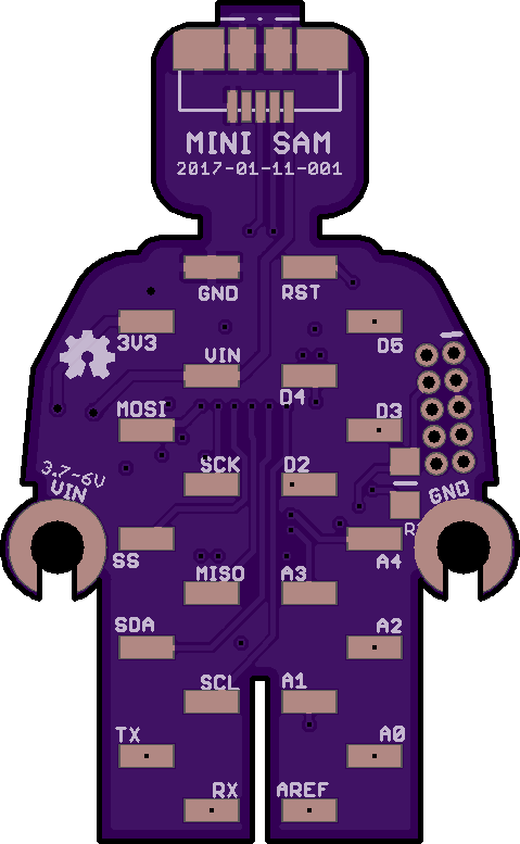
MINI_SAM_TQFP_2.54_BB_2017_01_12_001.brd
by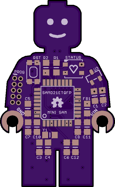
4
layer board of
0.96x1.55
inches
(24.36x39.47
mm).
Shared on
January 16th, 2017 14:34.
This is a LEGO minifigure sized development board using an Atmel SAMD21E M0 chip. I basically followed the recommended layout/setup from the SAMD21 spec sheets.
R3 may or may not be needed during programming.
SDA/SCL lines have 4.7k pull-up resistors
Included a 3.5mm WS2812B LED for fun.
This version has two 2.54mm pitch SMT connectors for a protoboard friendly design.
More details on Github