
OSH Park
Profile for robing
Shared projects
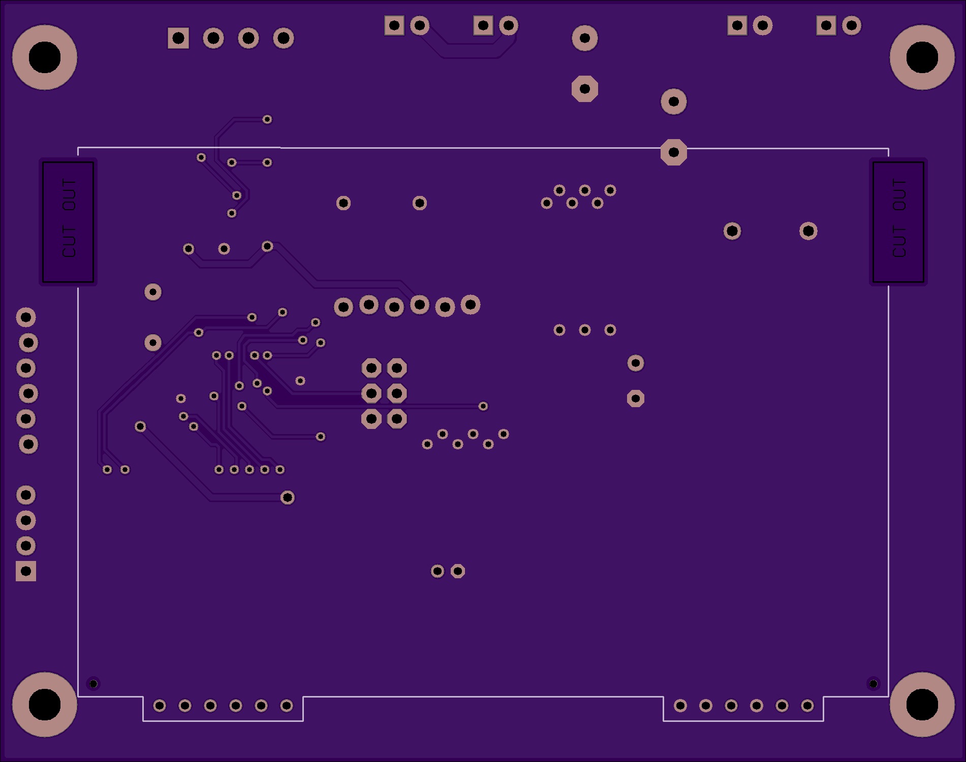
T962A Reflow Oven Controller
by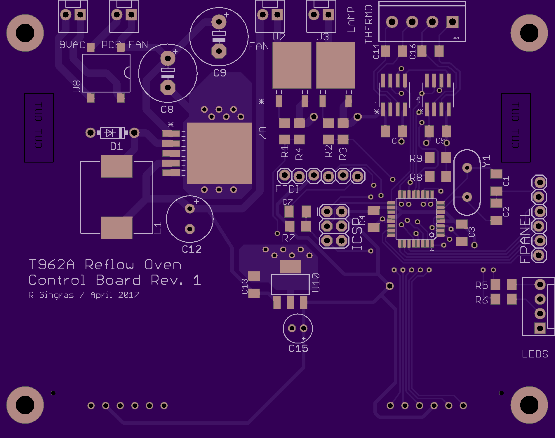
2
layer board of
3.80x3.00
inches
(96.55x76.20
mm).
Shared on
April 18th, 2017 21:15.
Parts List:
Note: Final parts list will be updated once the new boards are tested.
- LCD Display: DigiKey part number NHD-C12864A1Z-FSW-FBW-HTT-ND
- Atmel ATmega328p Microcontroller: DigiKey part number ATMEGA328P-AU-ND
- MAX31855 Thermocouple-to-Digital: DigiKey part number MAX31855KASA+-ND
- Fixed Inductor: DigiKey part number SRR1280A-331KCT-ND
- MOSFET: DigiKey part number 497-3157-1-ND
- 5V Regulator: DigiKey part number LM2575S-5.0/NOPB-ND
- 3.3V Regulator: DigiKey part number 497-13047-1-ND
- Bridge Rectifier: DigiKey part number 641-1348-5-ND
Design
My version of the T962A came with a Solid State Relay to control the lamps, and a simple BT139 triac circuit to control the fan. Based on another controller board by ESTechnical, I opted to use a dual SSR configuration to control the lamp and fan. These SSRs are driven by MOSFET switches on the control board. Two thermocouple-to-digital ICs provide the temperature readings, and the board also takes care of driving the tiny PCB fan and the status indicators. A smaller, more compact LCD screen based on the ST7565 was used in favor of the parallel interface of the included LCD screen. The board is controlled by an Atmel ATmega328p microcontroller.
I opted to forgo an onboard FTDI solution for now, that will be included in a later revision. There is a header for an FTDI cable on the board, used for programming and communication with the PC-based software.
Modifying the Oven
It is relatively simple to make just a few modifications to the oven and, along with the control board, improve the performance well beyond what you get out of the box. The steps are outlined below:
- Remove the infamous masking tape in and around the insulation.
- Disconnect and remove the existing LCD and controller boards.
- Re-connector a few leads and make a new cable to connect the fan SSR.
- Re-position the existing SSR and install the second SSR.
- Install the new control board.
- Connect the SSRs, power, PCB fan, LEDs, buttons and thermocouples to the control board.
- Reassemble the oven.
Programming
The board is compatible with the Arduino Pro 3.3V 8MHz bootloader. Use an ISP programmer (or Arduino as ISP) to write the bootloader, then you can upload the firmware (or write your own) through Arduino, PlatformIO or your environment of choice.
Use
Software is still under development…