OSH Park
AD8495 K-Type Thermocouple Amplifier
- You need to sign in or sign up before continuing.
AD8495 K-Type Thermocouple Amplifier
by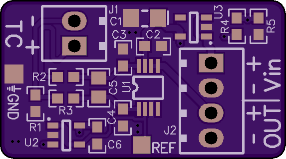
2
layer board of
1.15x0.64
inches
(29.11x16.13
mm).
Shared on
January 28th, 2014 06:36.
Cost: $3.60 for three.
Description:
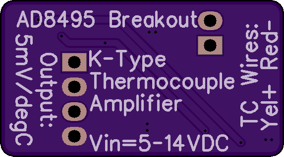
Breakout board for the Analog Devices AD8495CRMZ K-Type Thermocouple Amplifier. This IC reads thermocouple input and scales it to 5mV (0.005V) per °C (plus a 1.25V reference offset). This output can be read by a microcontroller or a multimeter; simply subtract 1.25 from the output, then multiply by 200 to get the temperature.
U3 (Texas Instruments LP2980) is a 4.7V low dropout linear regulator which provides Vcc for U1 (Analog Devices AD8495) and U2 (Analog Devices AD8613), and also feeds a voltage divider comprising R4 and R5. 1.25V from this divider is buffered through op-amp U2 to the reference pin of U1, providing a positive offset to allow measurement of negative temperatures. The thermocouple inputs to U1 are configured with a 1kHz low pass filter for noise rejection.
This board offers a measurement range of about -25 to +400°C with maximum error of +/-2°C. Measurements are possible outside this range (roughly -200 to +900°C), with larger errors due to thermocouple nonlinearity.
An exposed ground pad is provided near the thermocouple connector for ambient temperature sensing or debugging (see AD8495 datasheet, page 13). For permanent configuration as an ambient temperature sensor, use the AD8494CRMZ instead, as its output is more linear in this configuration.
Bill of Materials:
- U1: Analog Devices AD8495CRMZ K-Type Thermocouple Amplifier (8-MSOP) – NOTE: Both Mouser and Newark have this part in stock at lower prices.
- U2: Analog Devices AD8613AUJZ-R2 Operational Amplifier (SOT-23-5)
- U3: Texas Instruments LP2980AIM5X-4.7 4.7V LDO Linear Regulator (SOT-23-5)
- C1: AVX Corp F931C106KAA 10µF 16V Tantalum Capacitor (1206)
- C2, C6: Kemet C0603C104K4RACTU 0.1µF 16V Ceramic Capacitor (0603)
- C3, C4: Taiyo Yuden TMK107BJ105KA-T 1µF 25V Ceramic Capacitor (0603)
- C5: Yageo CC0805KKX5R5BB106 10µF 6.3V Ceramic Capacitor (0805)
- R1: Stackpole RMCF0603FT1M00 1MΩ 1/10W 1% Resistor (0603)
- R2, R3: Stackpole RMCF0603FT160R 160Ω 1/10W 1% Resistor (0603)
- R4: Stackpole RMCF0603FT31K6 31.6kΩ 1/10W 1% Resistor (0603)
- R5: Stackpole RMCF0603FT11K5 11.5kΩ 1/10W 1% Resistor (0603)
- J1: On Shore Technology OSTVN02A150 2-Position Screw Terminal
- J2: On Shore Technology OSTVN04A150 4-Position Screw Terminal -or- Sullins Connector PREC004SAAN-RC 4-Position Pin Header
BOM Cost: $12.83 + Thermocouple
K-type thermocouples and in-line connectors are available on eBay for $1.25 or less, delivered. Female panel-mount connectors are available from Auber Instruments for a few dollars.
Notes:
Input voltage should be a minimum of 5VDC to a maximum of 14VDC. Current draw is less than 3mA. My board runs perfectly on a 9V battery. U3 dropout voltage is maximum 225mV, so any Vin below about 4.925V may affect accuracy. If you power the board from a 5V source, measure voltage at U3 pin 1 to ensure adequate Vin.
Do not substitute alternate parts for C1. U3 is sensitive to ESR and this cap was selected to fall within its permitted range. C1 is a polarized capacitor; ensure that the mark on this device matches the mark on the board (bar to the right).
For best accuracy, use K-type thermocouple wire (chromel/alumel) all the way to the board. If you use a panel-mount connector on an enclosure, use additional K-type wire (available here or here) from the connector to the board. It may be cheaper to buy an extra thermocouple on eBay and cut off the wire you need.
For maximum temperature calculation accuracy, measure the voltage at the pad marked “REF”. This is the reference offset voltage, which is nominally 1.254V but which may differ due to LDO, resistor and op-amp tolerances. This exact measurement should be subtracted from the output before multiplying by 200. On my board, with Vin=9V, REF measures 1.2487V
For complete information on using this board with a microcontroller and compensating for thermocouple nonlinearity, see this application note.