OSH Park
Doubler to fit in a tube #3
- You need to sign in or sign up before continuing.
Doubler to fit in a tube #3
by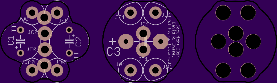
2
layer board of
2.39x0.72
inches
(60.78x18.31
mm).
Shared on
May 21st, 2014 18:06.
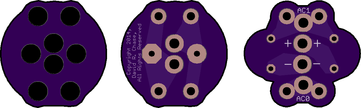
Modified Greinacher doubler, 3 by ¾ diameter (plus extra shim). Intended to use SB540 diodes (they’re large, but they are intended to physically butt against the smaller capacitors) and 16V electrolytic caps, preferably Digikey parts
http://www.digikey.com/scripts/DkSearch/dksus.dll?Detail&itemSeq=150331853 (8mm diameter, 5mm lead spacing, 1000 uF)
and
http://www.digikey.com/scripts/DkSearch/dksus.dll?Detail&itemSeq=150249397 (18mm diameter, 7.5mm lead spacing, 10000 uF).
The central connections are sized to allow use of either 14 gauge wire or 1/16 inch tubing; the tubing would allow you to connect the two boards, and mount a 3.5mm terminal block across the four holes (AC input on the inside, DC output on the outside).
The circuitless board is intended to fit between the large end capacitor and the board to which it connects, to prevent inadvertent shorts to the other connections on that board.
The intended assembly order is (1) solder diodes and wires to the underside of the mostly-circular board, trimming connections on the top side, (2) fit circuitless shield and then solder large capacitor into place, (3) fit small capacitors etc into irregular board, perhaps shimming/shield with kapton tape, and (4) solder irregular board into place.
It is best to position the diodes closer to the round board, but still leaving enough so that there is enough room for them to connect to the irregular board with clearance for the smaller caps. This is so that the tops of the capacitors will be wedged against the diodes with less chance for wiggling.
This is suitable for powering between 1 and 4 power LEDs in series (4 x 3.5V Vf is 14 volts, the caps are rated at 16 volts, don’t push your luck). The power source is AC from either a sidewall or hub dynamo; both of these are inherently current-limited so it is not possible to burn out the LEDs. Any on/off switch inserted into the circuit should be on the AC (power input) side; removing the DC load will result in high voltages exceeding the ratings of the capacitors. Care should be taken using this to supply a switching power supply, because those can also “refuse current”, which will also result in high voltages (and the higher the voltage, the more current they refuse).