OSH Park
PiAmp: Raspberry Pi FM transmitter amp and filter
- You need to sign in or sign up before continuing.
PiAmp: Raspberry Pi FM transmitter amp and filter
by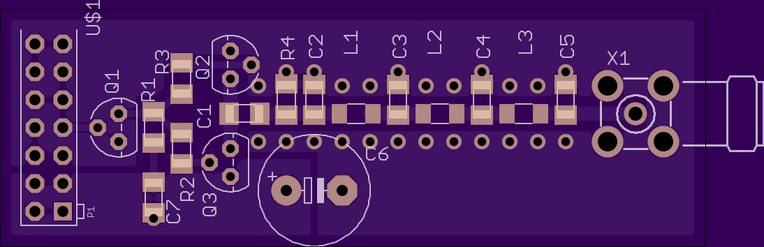
2
layer board of
2.53x0.85
inches
(64.16x21.62
mm).
Shared on
December 17th, 2014 17:55.
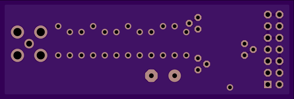
WARNING I forgot a resistor between the Pi and the base of Q1. You can still use this board if you’re willing to do a little hackery (put a 1k between the Pi and the base of Q1), or if you only want the filter section. I suspect I’ll re-release a fixed version of this at some point.
A digital amplifier for GPIO4 on a Raspberry Pi, followed by a 7 pole low pass filter to clean up the signal. I don’t know if the amp will work, these are my prototype boards to test. The idea is to treat GPIO4 as a DIGITAL signal, amplify accordingly, then filter when done. I honestly have no idea whether this will work. Worst case, leave off Q1-Q3, R1-R3, and jumper from the input at Q1 to the output at Q3 or Q2 and just use the filter section of the board. Your RF neighbors will be glad you did.
I modeled this amp after a CMOS logic gate: complimentary gates always either off or in saturation, and only dissipating heat during the transition. Faster transistors (than 2N3904/6) will hopefully be more efficient. GPIO4 is a 3.3v signal, but the 3.3v supply can only give 50mA. To use the 5v supply and be able to turn Q3 off, I first needed to amplify the 3.3v signal from GPIO4 to a 5v signal, which is what Q1 does. I’m honestly not sure whether the 470ohm R1 will pull Q3 out of saturation quick enough, so we’ll see how that goes.
This can be used on any band, but the values below were calculated for a -3db point of 150MHz for use on the 2m Ham Bands. Combine with something like WsprryPi or nbfm (proper download link) and you’ve got something potentially really useful.
Parts:
- C1: .01uF
- C2, C5: 9.1pF
- C3, C4: 39pF
- C6: 680uF
- C7: 10uF (I had these laying around, so I didn’t order them and therefore don’t have a link handy.)
- L1, L3: 64nH
- L2: 100nH
- R1: 470
- R2, R3: 1k
- R4: 10k
- SMA Connector
- Q1, Q2: 2N3904, or similar NPN BJT. (I also had these laying around so don’t have links for you) You might want to go with something better for RF.
- Q3: 2N3906, or whatever the PNP counterpart is to whatever you go with for Q1 and Q2.
Disclaimer: I list components here for a low pass cut-off of 150MHz for use on the 2m ham bands. Using these values for lower bands (ahem 3m, FM broadcast) will work, but you won’t be filtering nearly as well and will still be putting out gobs and gobs of harmonic noise and probably pissing off other legitimate users, ESPECIALLY if you are using the amplifier here. You’ll attract a lot less attention by re-calculating the values of C2-C5 and L1-L3 for a cut-off of about 110MHz (or lower, if you know you’ll be using the lower part of the band.) To be clear: transmitting on the FM broadcast band without a license is illegal (at least here in the US), but if you’re going to use my board to do it, I’d rather you do it cleanly.