OSH Park
Shared projects
- You need to sign in or sign up before continuing.
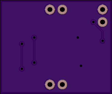
Divide by 3 v2.0
by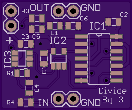
2
layer board of
0.90x0.75
inches
(22.89x19.05
mm).
Shared on
March 12th, 2017 18:32.
Adds a self-biased inverter on the input and PI network LPF on the output. The input can be sine or square and the output will be ~13 dBm sine.
- IC1 - 74LS74D Dual D flip-flop
- IC2 - 74AHC1G86DBV Single 2-input XOR
- IC3 - 74LVC2G04 Single inverter
- C1-C3 - 0.1µF
- C4 - 10 pF
- R1 - 1 MΩ
- R3 & R4 - 50 Ω
- L1 - 1.2 µH
- C5 & C6 - 220 pF
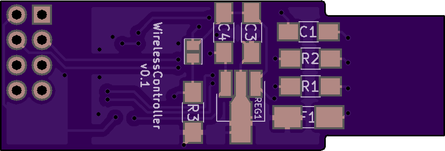
ReceiverUnit
by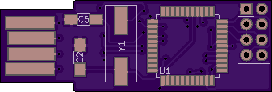
2
layer board of
1.76x0.60
inches
(44.75x15.16
mm).
Shared on
March 12th, 2017 17:06.
Wireless PS2 controller using an ATmega328p, nRF24l01+ radio, IMU, and batteries. This is the receiver unit that will receive the data from the PS2 controller’s tramitter unit. Rest of the project here.
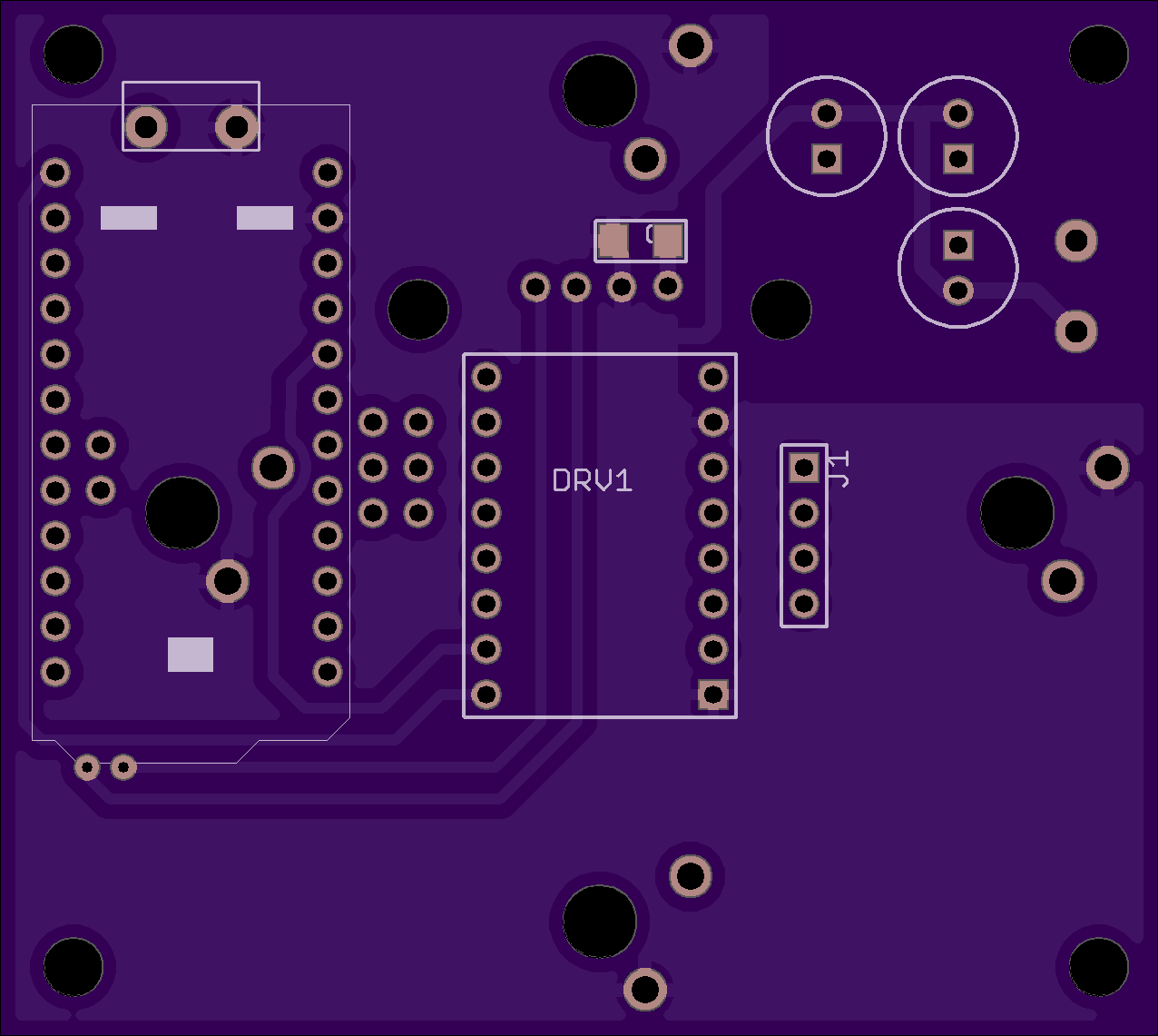
boxEEbotV1.brd
by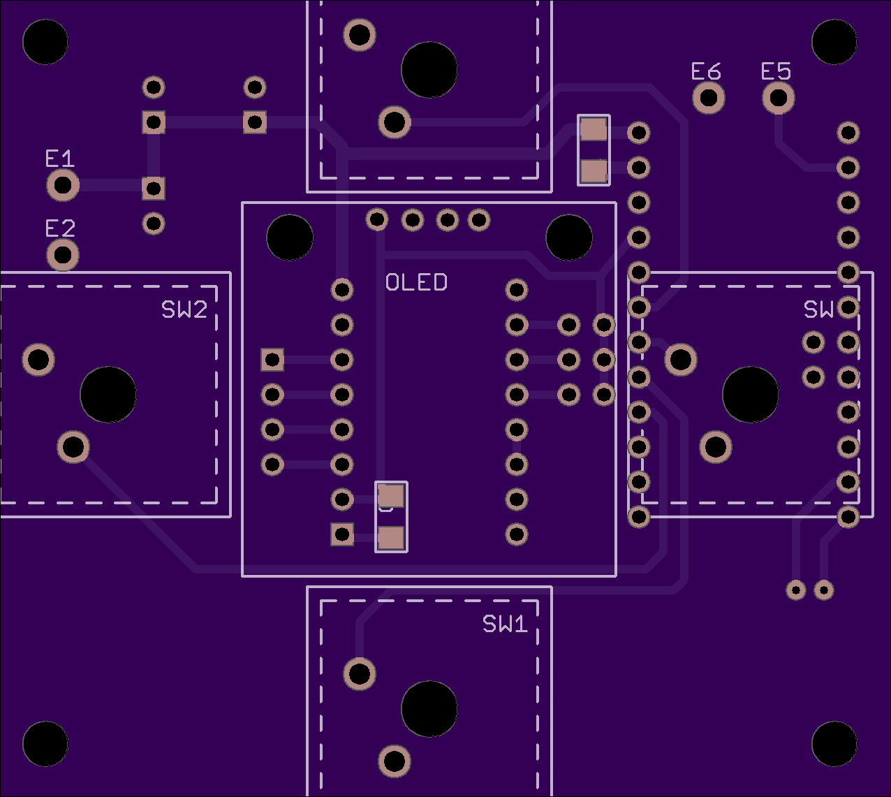
2
layer board of
2.55x2.28
inches
(64.77x57.91
mm).
Shared on
March 12th, 2017 16:03.
Trinket Pro +OLED Display + A4988 StepStick + 4 Cherry MX switches + Home Switch. Good board to control a stepper for one axis.
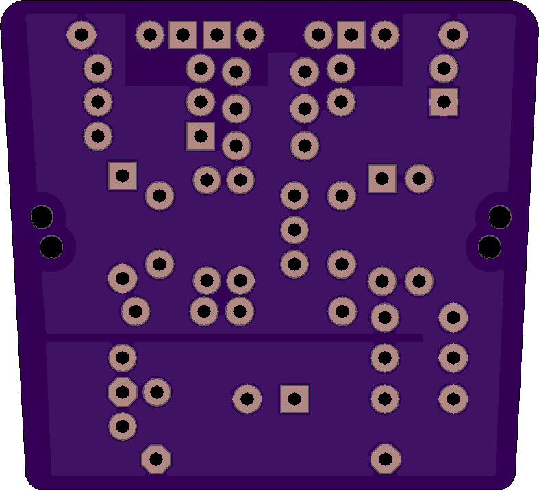
Multipattern condenser microphone oscillator
by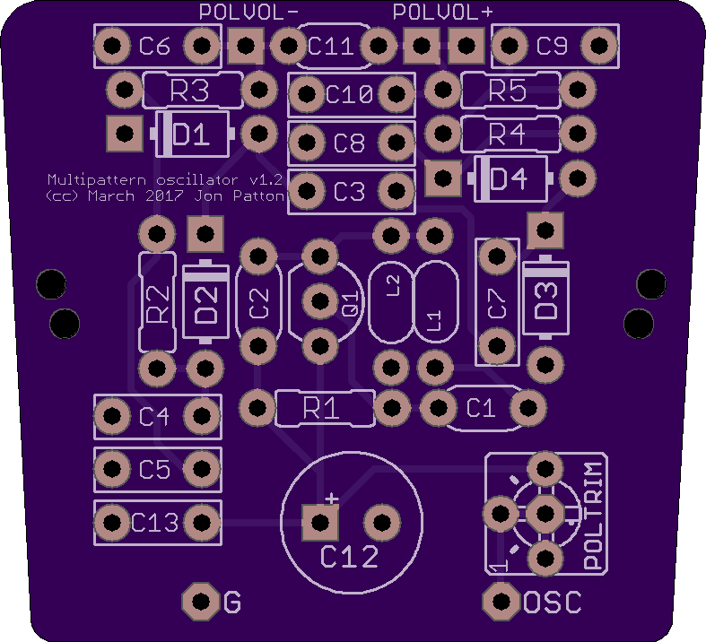
2
layer board of
1.57x1.43
inches
(39.95x36.37
mm).
Shared on
March 12th, 2017 15:30.
Creates adjustable +- polarization voltages for multipattern condenser microphone capsules.
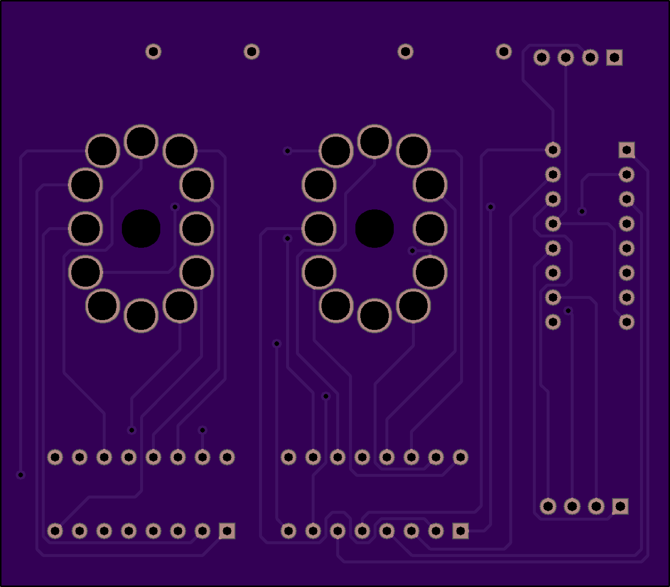
2 Tube Nixie Breakout
by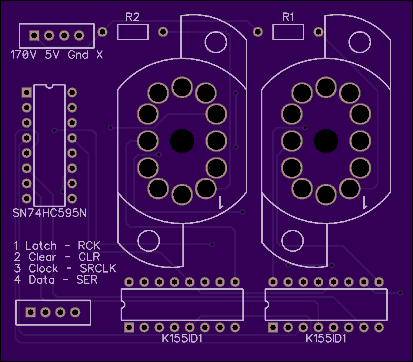
2
layer board of
2.73x2.39
inches
(69.22x60.63
mm).
Shared on
March 12th, 2017 14:37.
First Shared Project!
This is a simple 2-Tube breakout for socketed IN-12a nixie tubes. It is designed for each tube to be driven by a K1551D1 driver. The four inputs (A,B,C,D) of each driver is then routed to a SN74HC595N shift register. The Latch, Clear, Clock and Data pins of the 595 are externalized by pin connectors.
Input voltages are at the top of the board. 170 V, 5 V, and GND are expected. Please note that the 4th pin is not used. I also added resistors before the anodes of the tubes. At 170 V a 56K Ohm resistor should limit the current to 3 mA (.51 W, so use a 1 W resistor to be safe).