OSH Park
Shared projects
- You need to sign in or sign up before continuing.
Atari SIO23v3
by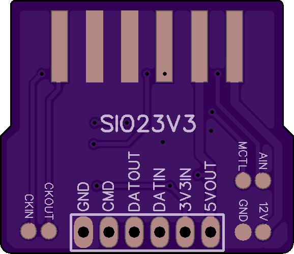
2
layer board of
1.16x1.00
inches
(29.36x25.35
mm).
Shared on
February 21st, 2017 20:43.
Description
The Atari SIO port runs at a 5V logic level. This board does down level shifting for connecting the Atari Data-In, Data-Out and Command lines to a microcontroller, Raspberry Pi or other device using logic levels less than 5V.
The board fits like an edge connector in between the two rows of pins in the Atari SIO port and is modeled after the Atari8Warez “Poor Mans SIO Cable”. The side labeled “SIO23V3” is the top/up side.
OSHPark boards are only 1.6mm thick which requires adding solder to the Atari SIO pads so they make contact with the pins. I don’t know exactly how much is needed, but it took several tries of adding more to get it just right.
So far, I have tested this board on my Atari 400 connected to an ESP-01 (esp8266, 3.3V). The Atari 400 5V output was able to keep the ESP-01 powered (thru a 3.3V voltage regulator) and connected to a bbs via telnet over Wifi using this modem emulator code.
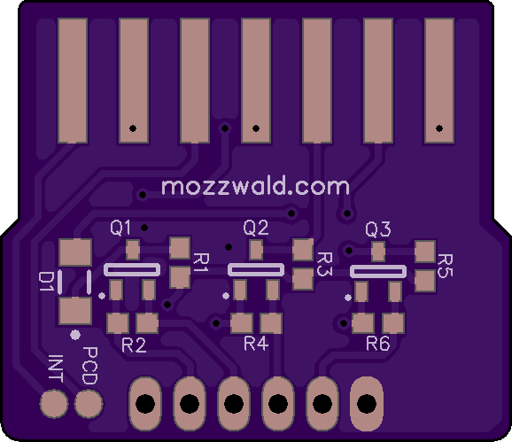
Part List
- D1: LL4150GS18 (or comparable)
- Q1-3: DMG2302U (or comparable)
- R1-R6: 10K 0603 5%
- 6 pin 0.1"/2.54mm Header (or directly soldered wires)
Pin Description
- GND: Ground
- CMD: Atari SIO Command Pin (level shifted)
- DATOUT: Atari SIO Data Out (to device RX, level shifted)
- DATIN: Atari SIO Data In (to device TX, level shifted)
- 3V3IN: Low voltage input (device logic level)
- 5VOUT: Atari 5V/Ready Output (can be used to as supply for low power microcontroller, current limit unknown)
Test Points/Pads
The remaining pins on the Atari SIO port are routed to test point pads on the board for experimenation. Keep in mind, these pads are directly connected to the Atari (no level shifting).
- CKIN: Clock In
- CKOUT: Clock Out
- MCTL: Motor Control
- AIN: Audio In
- GND: Ground
- 12V: +12V (Atari 400/800 only)
- INT: Interrupt
- PCD: Proceed
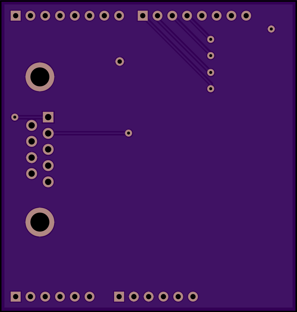
Yaesu G-5500
by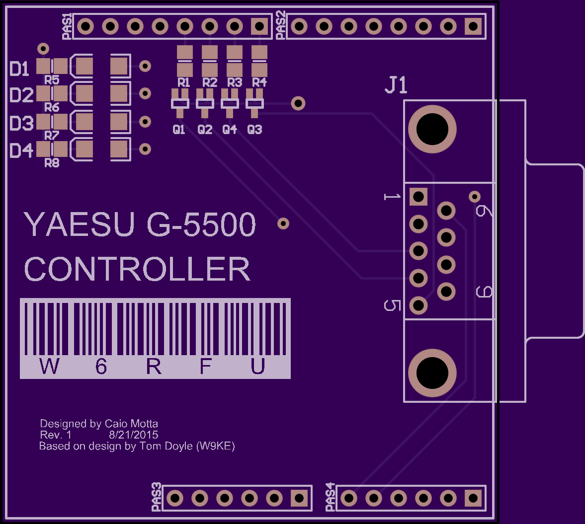
2
layer board of
2.01x2.11
inches
(51.05x53.62
mm).
Shared on
February 21st, 2017 19:58.
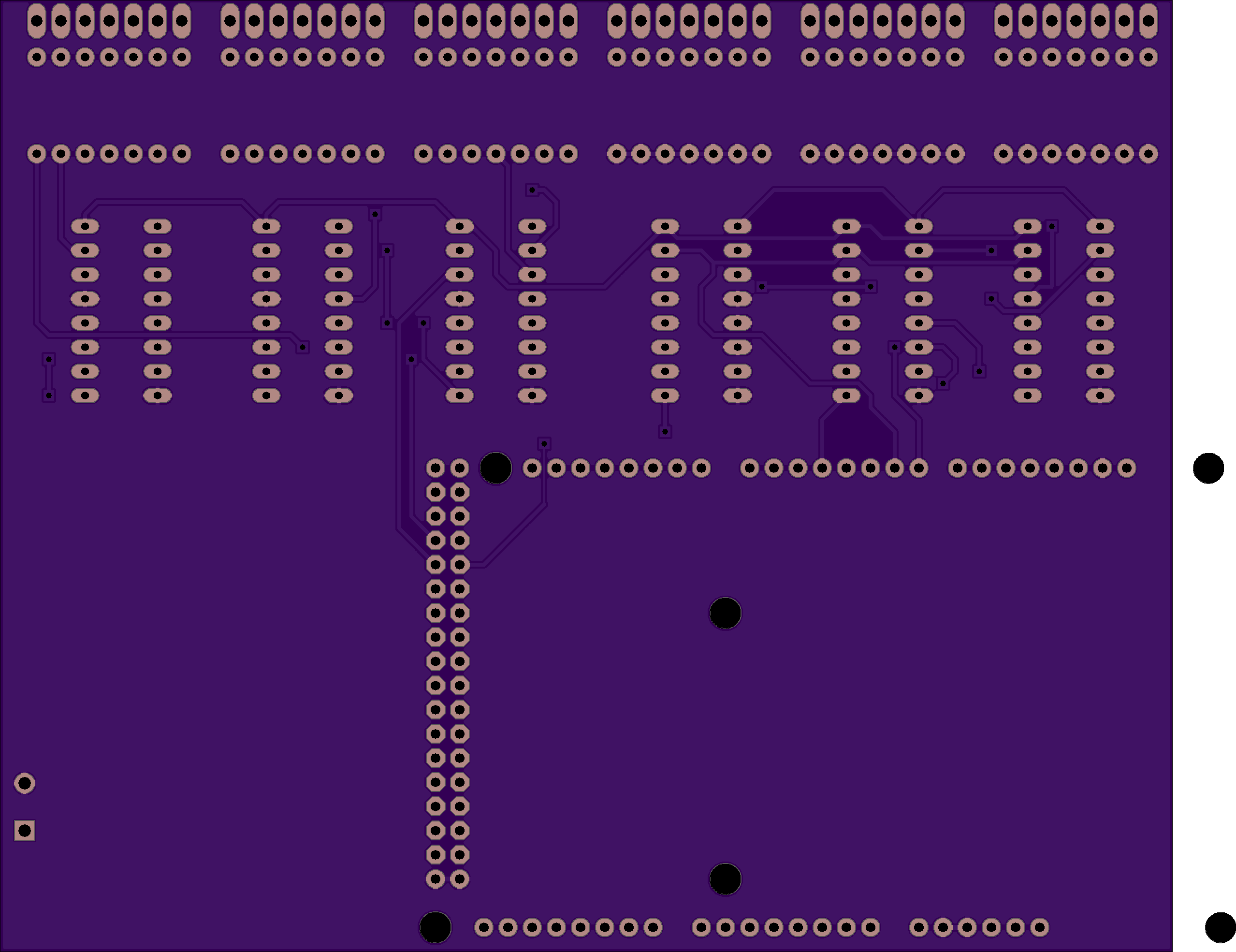
Arduino Shield
NOT FOR PRODUCTION - Sounds of Baseball
by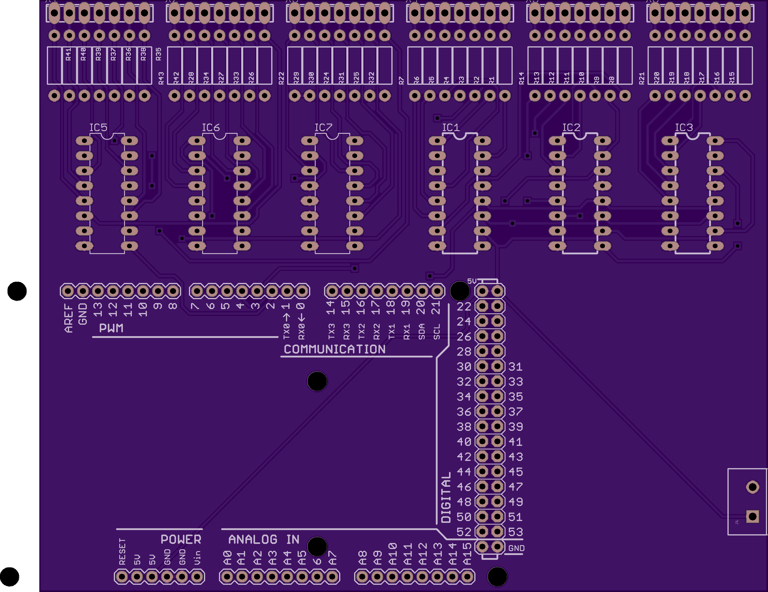
2
layer board of
5.11x3.94
inches
(129.87x100.00
mm).
Shared on
February 21st, 2017 18:43.
NOT FOR PRODUCTION - Minor changes must still be made
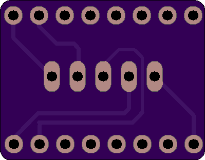
Powerlolu Pololu
by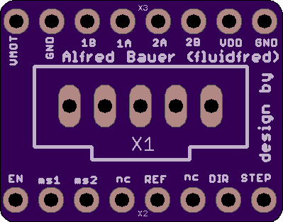
2
layer board of
0.80x0.62
inches
(20.22x15.82
mm).
Shared on
February 21st, 2017 08:59.
Powerlolu Pololu <-link to source
2 layer board of 0.80x0.62 inches (20.22x15.82mm). $2.45 for three.
High Power Pololu Board (Powerlolu) based on A4989 - can be connected to RAMPS Pololu port
Description
Powerlolu can drive stepper motors up to 500 Watts, drawing currents up to 10 Amps. The existing Pololu boards found in common RepRap 3D printers are at their limits when driving the 2 Nema17 z-axis stepper motors in parallel.
Continuous z-axis movement can cause the board to overheat. These boards hardly drive stepper motors bigger than a Nema17. To avoid overheating or to drive larger motors a more powerful driver board is needed.
The Powerlolu board enables the use of bigger stepper motors for a wide range of uses. This could be the conversion of manual milling machines into computer controlled milling machines (CNC-Machines) using the affordable electronics such as Arduino and RAMPS. Building 3D printers with a larger print volume or with larger extruders would be possible.
Tested the design by connecting a Nema43 stepper motor by Nanotec Electronic (capable of 6.6 Amps per coil, Torque 2000Ncm, Weight 8,4kg) to a Powerlolu attached to a 3D printer’s RAMPS X-port.
A short video of the new driver can be seen on YouTube at https://www.youtube.com/watch?v=G9FWvhZI7rs .
After two hours of motor usage the Powerlolu board only got luke warm - however see Installation Note
The schematics for the Powerlolu driver are freely available at https://github.com/fluidfred/powerlolu.
Technical specifications:
3-wire control with DIR, STEP, Enable-signal, compatible to the Pololu board
Supply voltage of the stepper motor from 12V to 50V
Adjustable stepping via SMD-jumper, 1, 1/2, 1/4, 1/16 (default) steps
Precision pot to adjust the current limiter
no extra heat sink required due to passive cooling up to NEMA 23 stepper motors.
Molex snap-on connector for connecting the RAMPS board to the Powerlolu
Dimensions PCB: 75.5mm x 65mm
Important installation note:
Observe the heat emission when using stepper motors larger than NEMA 23. If necessary, implement a cooling system, i.e. heat sinks mounted at the power-Mosfets and a fan. Each individual Powerlolu should be protected by connecting an appropriate fuse between VBB (X2) and the power source of the stepper motor.
More installation notes can be found under http://wiki.germanreprap.com/en/handbuch/powerlolu concerning wiring with RAMPS and current limiter adjustment.
Powerlolu
by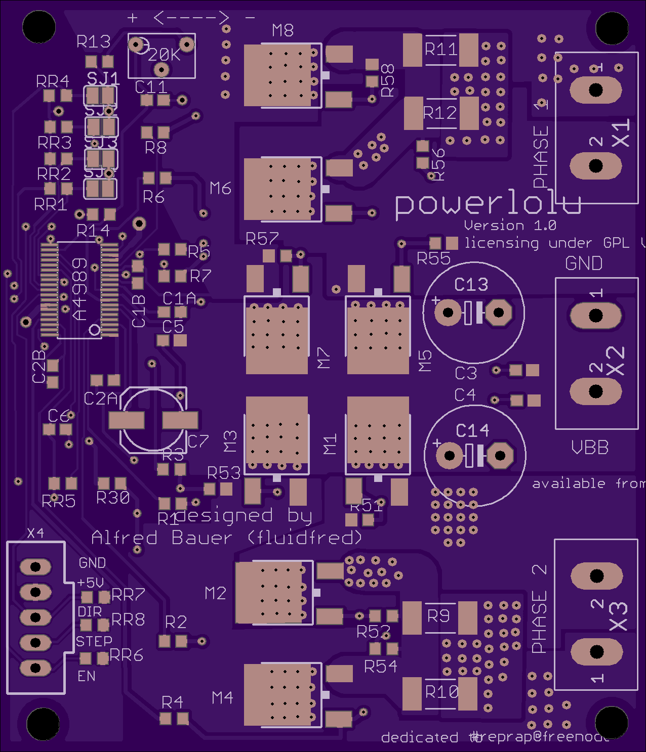
2
layer board of
2.55x2.97
inches
(64.77x75.51
mm).
Shared on
February 21st, 2017 08:59.
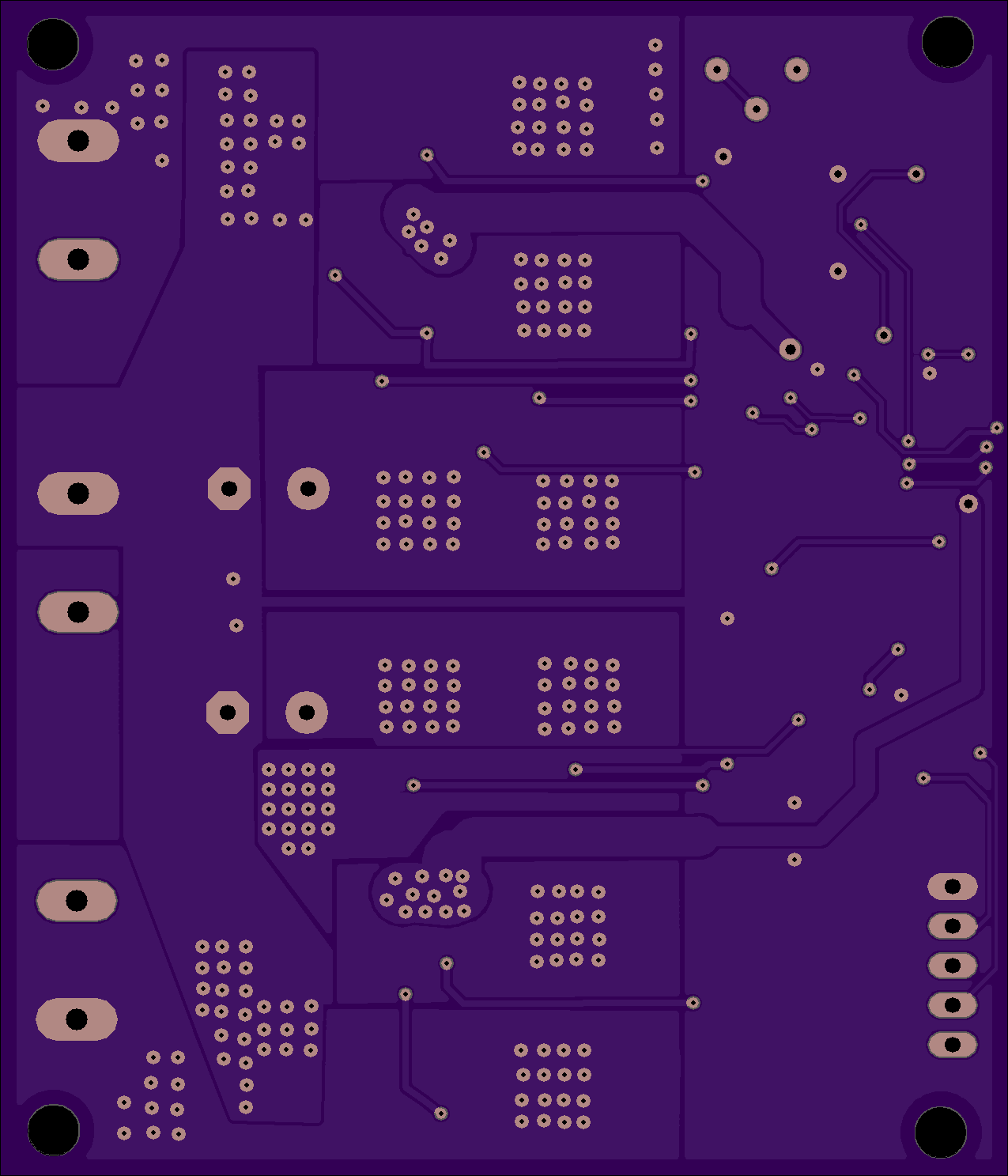
Powerlolu <-link to source
2 layer board of 2.55x2.97 inches (64.77x75.51mm). $37.90 for three
High Power Pololu Board (Powerlolu) based on A4989 - can be connected to RAMPS Pololu port
Description
Powerlolu can drive stepper motors up to 500 Watts, drawing currents up to 10 Amps. The existing Pololu boards found in common RepRap 3D printers are at their limits when driving the 2 Nema17 z-axis stepper motors in parallel.
Continuous z-axis movement can cause the board to overheat. These boards hardly drive stepper motors bigger than a Nema17. To avoid overheating or to drive larger motors a more powerful driver board is needed.
The Powerlolu board enables the use of bigger stepper motors for a wide range of uses. This could be the conversion of manual milling machines into computer controlled milling machines (CNC-Machines) using the affordable electronics such as Arduino and RAMPS. Building 3D printers with a larger print volume or with larger extruders would be possible.
Tested the design by connecting a Nema43 stepper motor by Nanotec Electronic (capable of 6.6 Amps per coil, Torque 2000Ncm, Weight 8,4kg) to a Powerlolu attached to a 3D printer’s RAMPS X-port.
A short video of the new driver can be seen on YouTube at https://www.youtube.com/watch?v=G9FWvhZI7rs .
After two hours of motor usage the Powerlolu board only got luke warm - however see Installation Note
The schematics for the Powerlolu driver are freely available at https://github.com/fluidfred/powerlolu.
Technical specifications:
3-wire control with DIR, STEP, Enable-signal, compatible to the Pololu board
Supply voltage of the stepper motor from 12V to 50V
Adjustable stepping via SMD-jumper, 1, 1/2, 1/4, 1/16 (default) steps
Precision pot to adjust the current limiter
no extra heat sink required due to passive cooling up to NEMA 23 stepper motors.
Molex snap-on connector for connecting the RAMPS board to the Powerlolu
Dimensions PCB: 75.5mm x 65mm
Important installation note:
Observe the heat emission when using stepper motors larger than NEMA 23. If necessary, implement a cooling system, i.e. heat sinks mounted at the power-Mosfets and a fan. Each individual Powerlolu should be protected by connecting an appropriate fuse between VBB (X2) and the power source of the stepper motor.
More installation notes can be found under http://wiki.germanreprap.com/en/handbuch/powerlolu concerning wiring with RAMPS and current limiter adjustment.