
OSH Park
Profile for WarHawk-AVG
- You need to sign in or sign up before continuing.
Shared projects
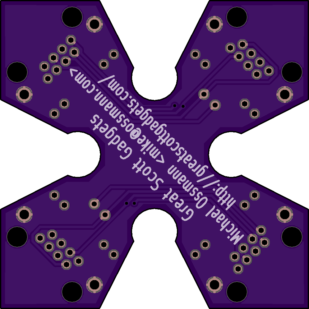
Throwing Star LAN Tap
by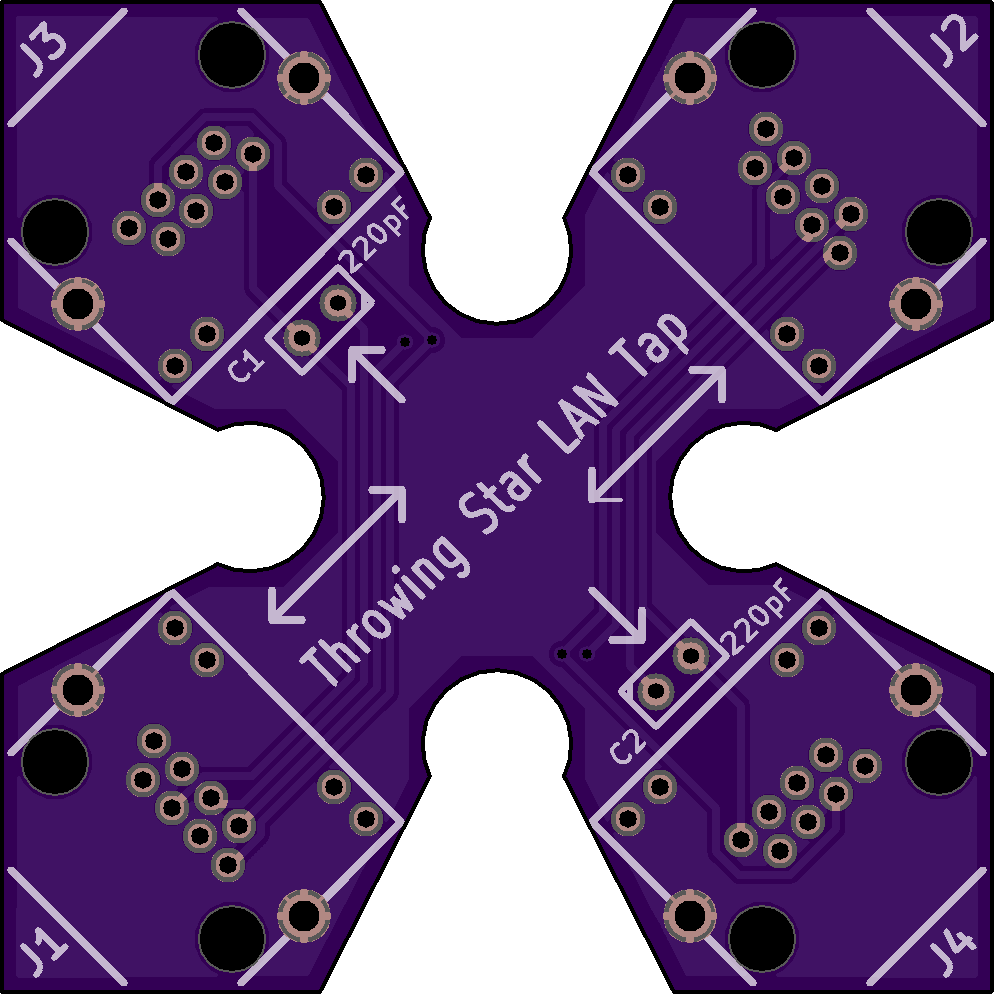
2
layer board of
1.99x1.99
inches
(50.50x50.50
mm).
Shared on
May 22nd, 2017 03:50.
Throwing Star LAN Tap
2 layer board of 1.99x1.99 inches (50.50x50.50 mm). $19.75 for 3
Opensource, you will have to source all the components yourself (part numbers and construction howto is in the link above), this is under the GNU GENERAL PUBLIC LICENSE Version 2
Best suggestion is to buy his kit…so he can continue to develop awesome open source hardware we all can use
Teensy 3.0 To Arduino R3 Shield
by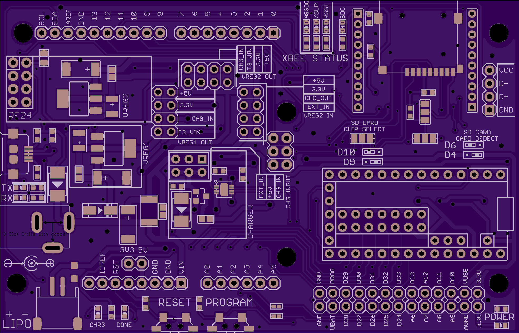
2
layer board of
3.94x2.53
inches
(100.00x64.16
mm).
Shared on
March 11th, 2017 05:33.
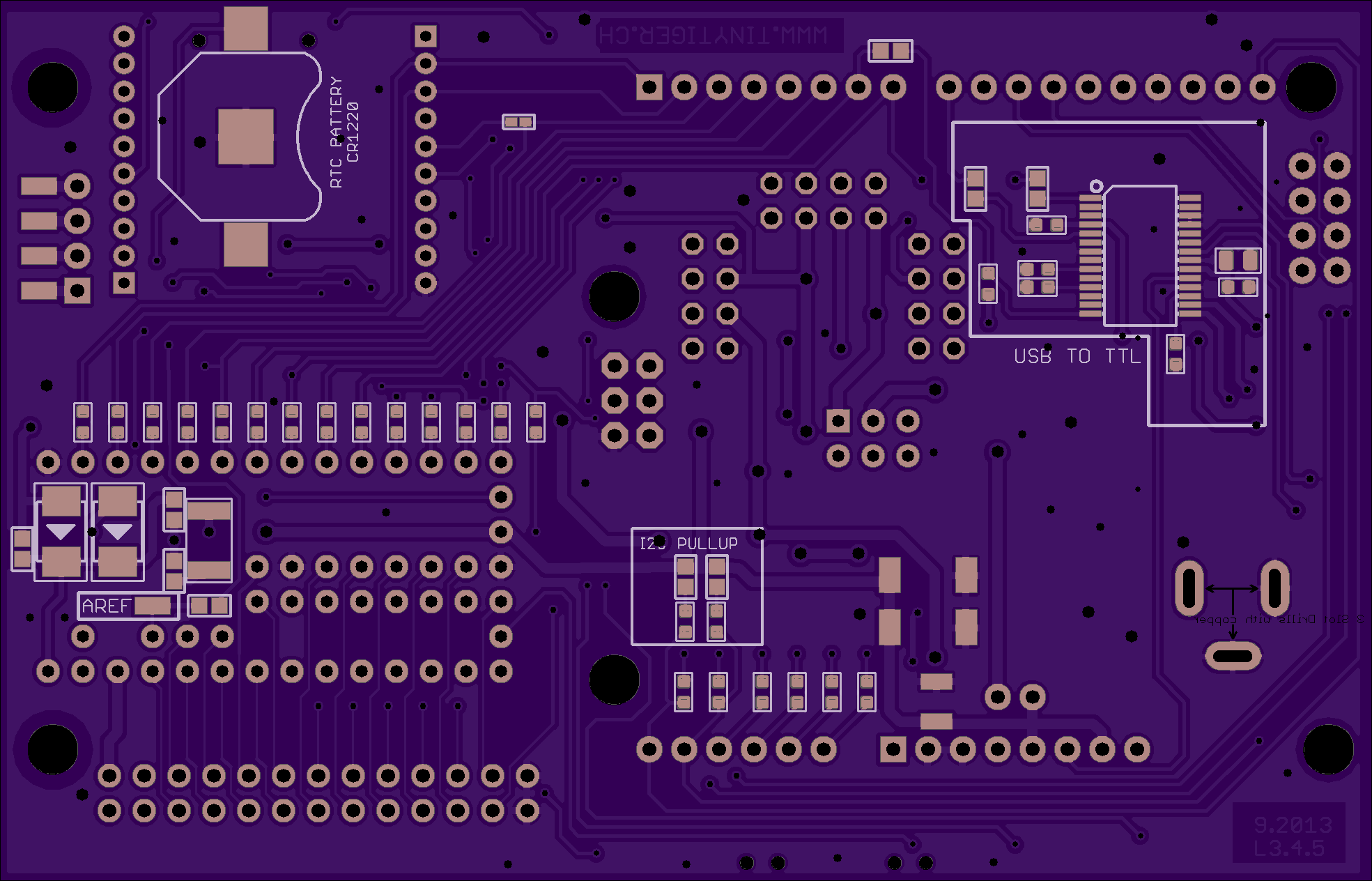
Teensy 3.0 To Arduino R3 Shield
2 layer board of 3.94x2.53 inches (100.00x64.16mm). $49.70 for three.
Teensy 3.0 to Arduino R3 breakout
Teensy 3.0 to Arduino R3 breakout Features
Arduino R3 Shield compatible header
All Teensy 3.0 pins accessible
Battery holder for the RTC
micro SD card holder
Reset/Program Button
I2C pullup resistors
external power supply
battery charger circuit
two dc dc converter (CJ1117)
XBee (pro) compatible socket
common nRF24L01(1) module pin header
USB to Serial converter (FT232RL) attached to Teensy Serial3
series resistors for all arduino R3 pins
most parts are from Seeedstudios (new) OPLV1 (for more information: http://www.seeedstudio.com/wiki/Open_parts_library))
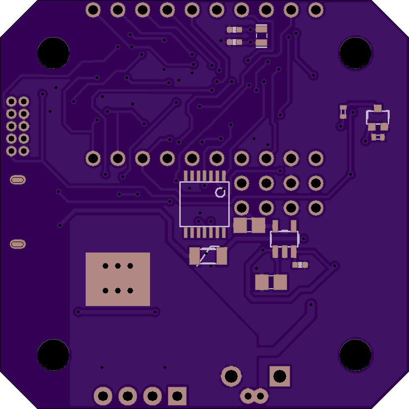
Mechaduino01
by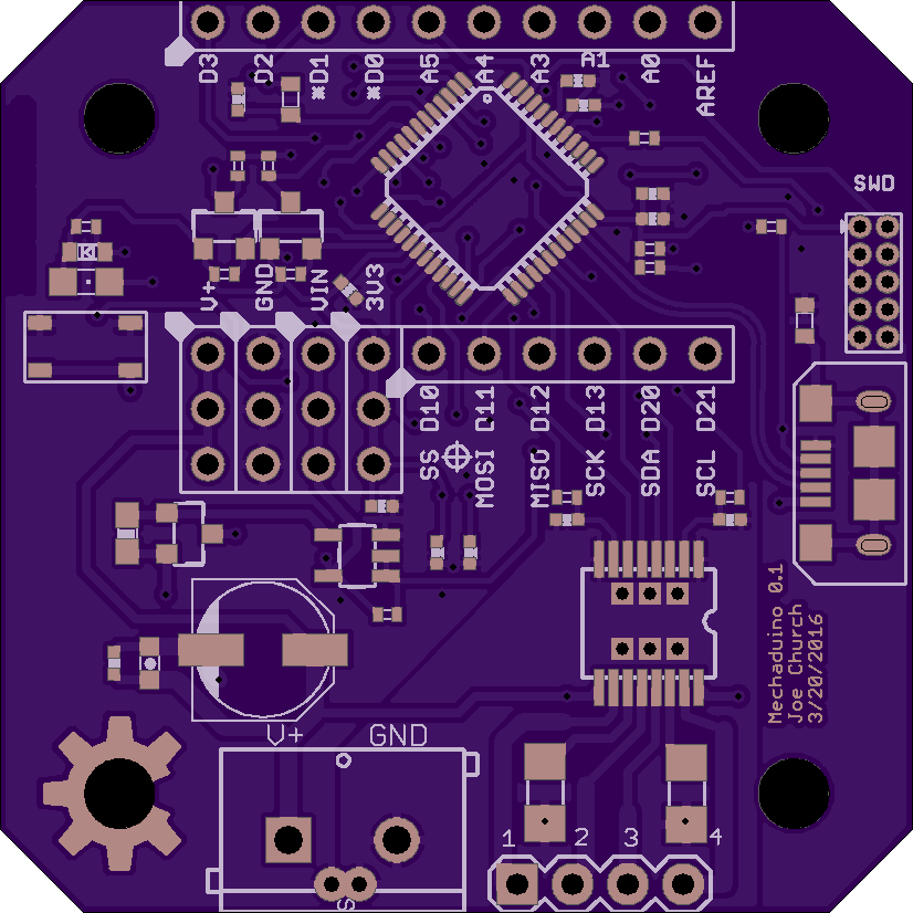
2
layer board of
1.65x1.65
inches
(41.94x41.94
mm).
Shared on
February 23rd, 2017 05:52.
2 layer board of 1.65x1.65 inches (41.94x41.94mm). $13.60 for three.
Engineers use servo motors to achieve the precision motion required in applications such as robotics, automation, and CNC manufacturing. Like RC servos, industrial servos actively correct for external disturbances. Unlike RC servos, industrial servos can provide very accurate motion, and often support advanced motion control modes. Unfortunately the cost of industrial servos is prohibitive to the individual maker (thousands of dollars per motor).
We’ve been developing an affordable open-source industrial servo motor, opening the door to sophisticated mechatronics applications. Our design leverages the low cost of mass produced stepper motors. We are able to achieve very high resolution via 14b encoder feedback (after calibration routine!).

Project Goals
Position, velocity, torque loops
Step & direction inputs for drop-in compatibility with stepper motors / step stick
I2c, serial inputs
Customizable/open source with access to internal variables
Transparent and user-definable control algorithms (commercial servos often lack this)
Arduino compatible with easy to use interface
High resolution pointing (sub 0.1 degree)
Low cost (should not be a huge leap from stepper + stepstick cost)
Serial interfaces for inter-motor communication
On-board processor allows for stand alone for simple applications
Adjustable commutation profiles
PID auto tuning
Anti-cogging capable
Open to customization. Outside of our firmware, we see Mechaduino as a very useful hardware package. If you would like to use the stepper motor in open loop mode w/ encoder to verify location, you can do that.
Strategy
An industrial servo motor can be broken down into four main components (below). First we looked at each of these components and tried to piece together an affordable breadboard-level prototype. After some experimentation, we were able to distill out a working lineup of components. From there, we’ve been iterating on our design, working out all the kinks, and tuning the control loops. It’s starting to come together!
…Back to those four main components:
The actual motor, usually of the brushless dc variety. When you look at industrial servo motors, a big chunk of the cost is the motor itself. They are often custom built, or at least built in limited quantities, which means $$$. Watt for watt, I'd guess that a mass produced NEMA 17 or NEMA 23 stepper motor is between a tenth and a hundredth the cost of the BDC motors used in industrial servos. Although their design is optimized for "stepping," stepper motors are really just 50-pole brushless dc motors. They can be controlled exactly like a more traditional 3 phase BDC motor with more poles. So that's the plan. It's working!

A sensor for feedback, usually an encoder. Optical encoders are pretty standard, but get quite pricey if you want high resolution and/or absolute position information. We were intrigued by some of the cheap, high resolution magnetic encoders offered by vendors like AMS. It turns out that although they claim 12 and 14 bit resolutions (that's 0.09 and 0.02 degrees respectively), they suffer from non-linearities on the order of a degree or so! However, we found that this non-linearity is very repeatable, and we were able to develop a quick, self contained (on motor) calibration routine that restores resolution to better than 0.1 degrees. (More on this later. This was a significant design effort and is worthy of its own build log!)

Drive circuitry/power electronics to excite the motor windings. Many industrial servos use discrete H bridges. Each phase requires it's own H bridge ( for a two phase motor... half bridges for each in a three phase motor), which consists of at least 4 if not 8 (...including freewheeling diodes) discrete switching devices. Throw in gate drive circuitry, and things start to get expensive. We hoped to find a single-chip, integrated solution that would allow for current feedback, and we found just that in the A4954 dual full bridge PWM driver.

Control Electronics. Usually a microcontroller or FPGA. Early on, we decided that Arduino compatibility was a must in order to make the firmware as accessible as possible. We chose to use a SAMD21 ARM M0+ (Arduino Zero compatible) processor to balance cost and performance. Our breadboard prototype system verified that this processor was more than capable of executing the necessary algorithms.
Application Examples:
Fine, closed loop positioning for 3D printers
Fine pointing for optics (laser, telescope, camera gimbal)
Velocity loop for a record player
Force feedback/impedance control for robotics
Force feedback for gaming controllers
Adjustable mechanical impedance: virtual spring,mass,damper
Electrical gearing between two axes on a cnc machine, etc.
Haptics
Tele-operation
Gravity-cancellation (counter the gravitational torques on a robotic arm for example)
Load detection and characterization (simple case: use as a scale!)
Paper towel/tp dispenser
Variable load (brake)
Variable load (generator)
After market valve control (automate a garden hose, etc)
Other Advantages:
Finer resolution than stepper motors (0.02 degrees)
True closed loop for disturbance rejection
Lower power consumption: only uses power to fight disturbances. This in turn means higher peak torque.
Absolute position control (not incremental). No need to home on power-on.
License
All Mechaduino related materials are released under the Creative Commons Attribution Share-Alike 4.0 License
I had some difficulty getting some of the aesthetics on the board, namely the silk of tropical labs and the Mechaduino in copper on the top layer…everything else is 100% as is from his github
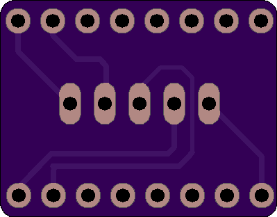
Powerlolu Pololu
by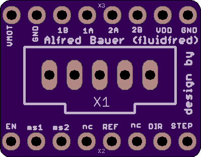
2
layer board of
0.80x0.62
inches
(20.22x15.82
mm).
Shared on
February 21st, 2017 08:59.
Powerlolu Pololu <-link to source
2 layer board of 0.80x0.62 inches (20.22x15.82mm). $2.45 for three.
High Power Pololu Board (Powerlolu) based on A4989 - can be connected to RAMPS Pololu port
Description
Powerlolu can drive stepper motors up to 500 Watts, drawing currents up to 10 Amps. The existing Pololu boards found in common RepRap 3D printers are at their limits when driving the 2 Nema17 z-axis stepper motors in parallel.
Continuous z-axis movement can cause the board to overheat. These boards hardly drive stepper motors bigger than a Nema17. To avoid overheating or to drive larger motors a more powerful driver board is needed.
The Powerlolu board enables the use of bigger stepper motors for a wide range of uses. This could be the conversion of manual milling machines into computer controlled milling machines (CNC-Machines) using the affordable electronics such as Arduino and RAMPS. Building 3D printers with a larger print volume or with larger extruders would be possible.
Tested the design by connecting a Nema43 stepper motor by Nanotec Electronic (capable of 6.6 Amps per coil, Torque 2000Ncm, Weight 8,4kg) to a Powerlolu attached to a 3D printer’s RAMPS X-port.
A short video of the new driver can be seen on YouTube at https://www.youtube.com/watch?v=G9FWvhZI7rs .
After two hours of motor usage the Powerlolu board only got luke warm - however see Installation Note
The schematics for the Powerlolu driver are freely available at https://github.com/fluidfred/powerlolu.
Technical specifications:
3-wire control with DIR, STEP, Enable-signal, compatible to the Pololu board
Supply voltage of the stepper motor from 12V to 50V
Adjustable stepping via SMD-jumper, 1, 1/2, 1/4, 1/16 (default) steps
Precision pot to adjust the current limiter
no extra heat sink required due to passive cooling up to NEMA 23 stepper motors.
Molex snap-on connector for connecting the RAMPS board to the Powerlolu
Dimensions PCB: 75.5mm x 65mm
Important installation note:
Observe the heat emission when using stepper motors larger than NEMA 23. If necessary, implement a cooling system, i.e. heat sinks mounted at the power-Mosfets and a fan. Each individual Powerlolu should be protected by connecting an appropriate fuse between VBB (X2) and the power source of the stepper motor.
More installation notes can be found under http://wiki.germanreprap.com/en/handbuch/powerlolu concerning wiring with RAMPS and current limiter adjustment.
Powerlolu
by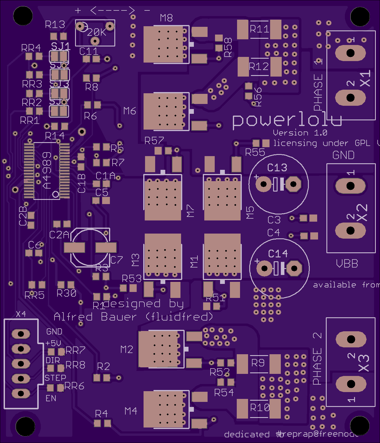
2
layer board of
2.55x2.97
inches
(64.77x75.51
mm).
Shared on
February 21st, 2017 08:59.
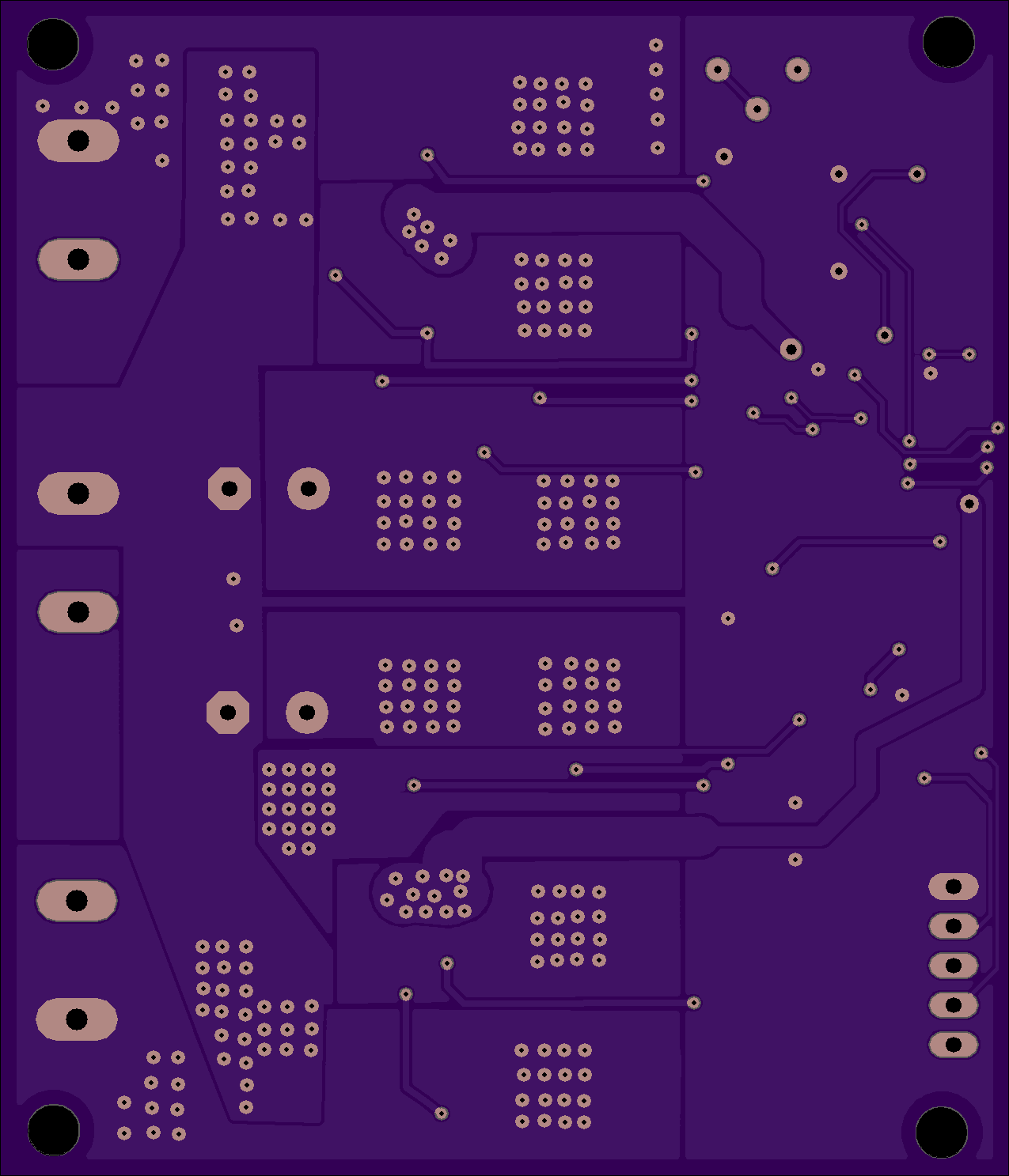
Powerlolu <-link to source
2 layer board of 2.55x2.97 inches (64.77x75.51mm). $37.90 for three
High Power Pololu Board (Powerlolu) based on A4989 - can be connected to RAMPS Pololu port
Description
Powerlolu can drive stepper motors up to 500 Watts, drawing currents up to 10 Amps. The existing Pololu boards found in common RepRap 3D printers are at their limits when driving the 2 Nema17 z-axis stepper motors in parallel.
Continuous z-axis movement can cause the board to overheat. These boards hardly drive stepper motors bigger than a Nema17. To avoid overheating or to drive larger motors a more powerful driver board is needed.
The Powerlolu board enables the use of bigger stepper motors for a wide range of uses. This could be the conversion of manual milling machines into computer controlled milling machines (CNC-Machines) using the affordable electronics such as Arduino and RAMPS. Building 3D printers with a larger print volume or with larger extruders would be possible.
Tested the design by connecting a Nema43 stepper motor by Nanotec Electronic (capable of 6.6 Amps per coil, Torque 2000Ncm, Weight 8,4kg) to a Powerlolu attached to a 3D printer’s RAMPS X-port.
A short video of the new driver can be seen on YouTube at https://www.youtube.com/watch?v=G9FWvhZI7rs .
After two hours of motor usage the Powerlolu board only got luke warm - however see Installation Note
The schematics for the Powerlolu driver are freely available at https://github.com/fluidfred/powerlolu.
Technical specifications:
3-wire control with DIR, STEP, Enable-signal, compatible to the Pololu board
Supply voltage of the stepper motor from 12V to 50V
Adjustable stepping via SMD-jumper, 1, 1/2, 1/4, 1/16 (default) steps
Precision pot to adjust the current limiter
no extra heat sink required due to passive cooling up to NEMA 23 stepper motors.
Molex snap-on connector for connecting the RAMPS board to the Powerlolu
Dimensions PCB: 75.5mm x 65mm
Important installation note:
Observe the heat emission when using stepper motors larger than NEMA 23. If necessary, implement a cooling system, i.e. heat sinks mounted at the power-Mosfets and a fan. Each individual Powerlolu should be protected by connecting an appropriate fuse between VBB (X2) and the power source of the stepper motor.
More installation notes can be found under http://wiki.germanreprap.com/en/handbuch/powerlolu concerning wiring with RAMPS and current limiter adjustment.