OSH Park
Shared projects
PWM555.brd
by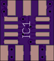
2
layer board of
0.35x0.40
inches
(8.92x10.16
mm).
Shared on
January 28th, 2017 22:43.
| Part(s) | Value |
|---|---|
| IC1 | TLC555 (can use NE555) |
| Q1 | AO3400 (can use other N-channel MOSFET) |
| bottom connector | GND, Vcc, anode, cathode |
| top connector | potentiometer according to PWM frequency |
| R1 | 1k |
| C1 | according to PWM frequency |
| C2 | 10nF (optional) |
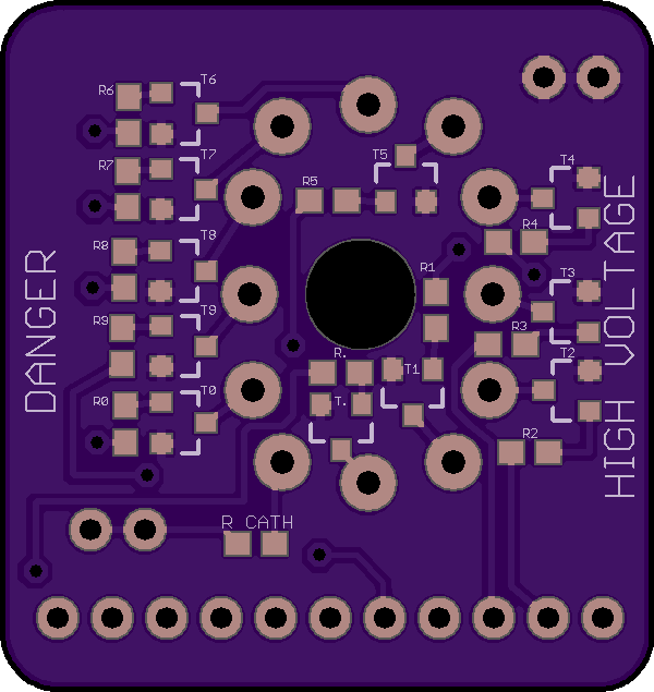
IN-12B breakout v2.1.brd
by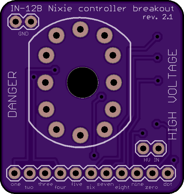
2
layer board of
1.20x1.27
inches
(30.53x32.28
mm).
Shared on
January 28th, 2017 20:51.
A very simple IN-12B Nixie breakout board
Parts needed
- 11 MMBTA42 transistors
- 12 30kOhm 0603 (Imperial) SMD resistors
- 12 1mm socket pins (can be found on Ebay)
- Some standard header pins (2 for GND, 2 for HV-IN, 11 for inputs)
Usage
- Provide ~180V between HV-IN and GND
- turn on any digit with a 3.3V or 5V logic input on corresponding pin
Known issues
- the additional GND and HV-IN header pins (for daisy chaining) may be blocked by the Nixie itself
Source files can be found on my Github. Feel free to submit PRs !
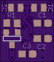
Resistor board
by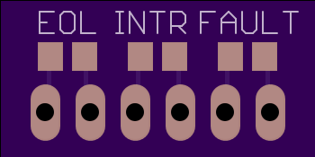
2
layer board of
0.70x0.35
inches
(17.78x8.92
mm).
Shared on
January 28th, 2017 11:42.
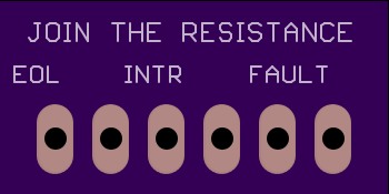
Resistor board for alarm systems
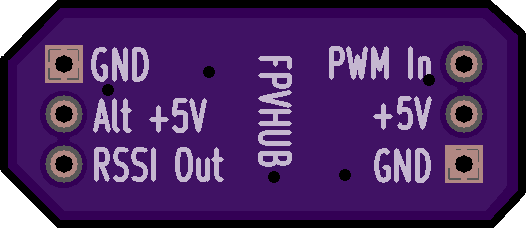
FPVHUB EZRSSI
by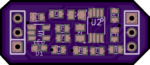
2
layer board of
1.05x0.46
inches
(26.70x11.58
mm).
Shared on
January 28th, 2017 09:39.
Analog rssi for EZUHF. Turns the EZUHF PWM signal into a 0 to 3V analog output. Now tested and working nicely
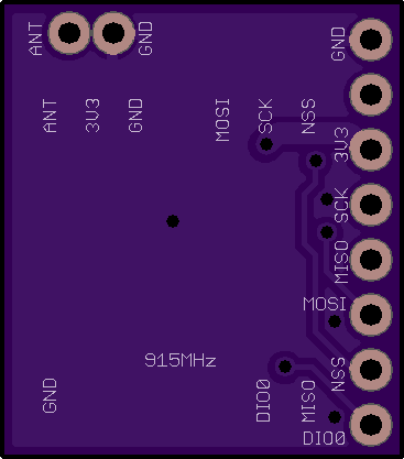
RFM69CW Breakout Board
by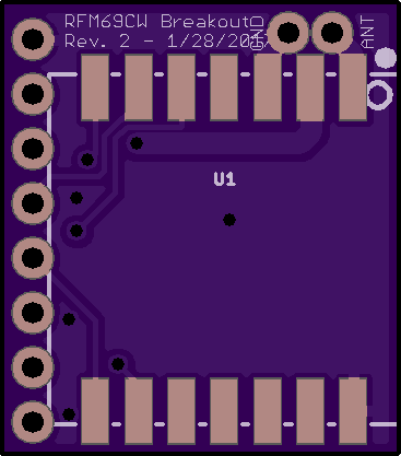
2
layer board of
0.74x0.83
inches
(18.69x21.16
mm).
Shared on
January 28th, 2017 09:38.
PURPOSE
Adapt the odd pad pitch of the RFM69CW or RFM69HCW to a breadboard friendly spacing and lay the pins out so that they match with the ATMega 328p-DIP ideally.
SIZE & COST
18.64mm x 21.16mm = $1.02 per board
DISCUSSION
An extremely small breakout board for adapting the odd pad pitch of the RFM69CW radio to breadboard friendly pin spacing. In particular some care was taken to place pins such that they work perfectly with an ATMega 328p-DIP (the chip in Arduinos). Used in this way, the board should span pins 15 through 22 on the 328p so as to match up MISO, MOSI, SS, SCK, VCC, and GND. The only other pin needed in some cirumstances is DIO0 which is mated up to PB1.