OSH Park
Zipit Z2 Breakout v2.0
- You need to sign in or sign up before continuing.
Zipit Z2 Breakout v2.0
by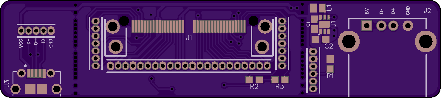
2
layer board of
2.96x0.66
inches
(75.11x16.69
mm).
Shared on
August 1st, 2016 22:18.
Zipit Z2 Breakout v2
Parts List
- C1, C2: 4.7uF 6.3V 0603 (C1608X5R0J475K080AB)
- L1: 1uH 0805 (LQM21PN1R0MC0D)
- U1: TI 5V Regulator (TPS61240DRVT)
- J1: Hirose to Zipit Connector (ST60X-36S)
- J2: USB Host Port (292303-1)
- J3: Amphenol FCI Micro USB Port (10118194-0001LF)
- R1: 10K ohm 0603 Resistors (Regulator Enable)
- R2, R3: 4.7k-10k ohm 0603 Resistors (I2C)
- 1.27mm Headers
Details
Both USB Ports are designed to be optionally broke off the middle section. Score the board with a blade on both sides down the line of holes and snap off the end. Each board when broken off can be used independently.
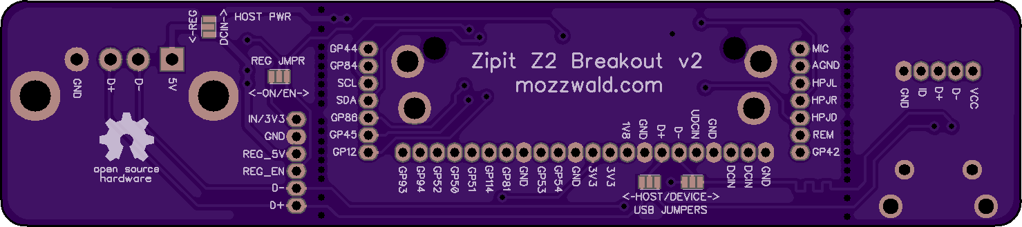
Main Zipit Board
This section of board contains the Hirose 36 pin connector, 1.27mm pitch headers, I2C resistors and “USB Jumpers”. The USB Jumpers allow connecting either the Micro USB (for device mode) or USB A (for host mode) port to the USB pins on the Zipit. The center pad of the jumper is connected to the Zipit. Bridge the center pad to the left or right pad with solder to set Host or Device mode.
USB-A Board
This section of board contains a USB A Port, 3.3V to 5V boost regulator, 1.27mm pitch header and jumper pads for the regulator and host power. When attached to the main Zipit board the “Host Pwr” Jumper sets which power is supplied to the port; DCIN from the Zipit or 5V from the regulator. The “Reg Jmpr” sets the regulator to be always “ON” or by toggling the “EN"able pin high (GPIO54 or via header).
Micro USB Board
This board contains a Micro USB port and 1.27mm pitch header. The VCC pin is connected to DCIN allowing you to power the Zipit via USB cable.