Welcome to OpenBuilds Community

Signup today and join in on the fun!

Sign Up

The Frog (not an acrynym!): CNC Router

Discussion in 'CNC Mills/Routers' started by Neil Rosenberg, Jan 3, 2014.
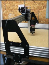
  1. zach

    zach New Builder

    Neil,
    Can you post the acceleration ramp for your 270 oz stepper motors? I asked automation technology, where I bought mine from, and they said to try it on Mach 3 because they don't have the acceleration ramps. I am using a usb controller and dont have mach 3.
  2. Neil Rosenberg

    Neil Rosenberg Journeyman Builder

    No problem.

    Having some trouble inserting full size images, please have a look in the build description photos, I'm putting them there.

    You may also be able to get them here:
    http://pho.to/4l64K/ma
    and
    http://pho.to/4l64j/ql

    The parameters may change when I switch to the 3mm GT2.
    Let me know if you can't read this, or need more info.

    Neil
    Last edited: Feb 15, 2014
  3. zach

    zach New Builder

    Neil,
    I am new to cnc and this forum. I am in the process of building my own cnc machine. How does someone go about finding the velocity and acceleration for the stepper motors if they are not provided with a acceleration ramp? How did you go about setting your acceleration ramp?
  4. Neil Rosenberg

    Neil Rosenberg Journeyman Builder

    Hi Zach, and welcome to the forum and to CNC machining!

    For me, some of the settings were calculated (steps/inch) and some were derived experimentally from driving the actual system (speed and ramps) by adding a load (my hand) and seeing where the step motors gave up.

    There is probably a range of values that would work fine, I just used my common sense and powers of observation to find a happy medium.

    Once you set the steps/inch, which is based on the number of steps/rev and inches(or mm) of motion per rev, you can start playing around with the maximum speed and slope of the ramps to see where your system works well.

    Neil
  5. zach

    zach New Builder

    Neil,
    Thank you for the information and the pictures, much appreciated.
  6. Neil Rosenberg

    Neil Rosenberg Journeyman Builder

    My pleasure, and good luck with your build :D.

    There's a great group of folks here, many with a LOT more experience than me in CNC, so if you get stuck be sure to post here or in any other discussion -- you're sure to get lots of help.
  7. The Dude

    The Dude Veteran Builder

    Dude, that is an incredible build. I love the magnetic dust brush, hollowed side braces, vacuum table, chain link wire guides, and heavy duty router. Would it be possible to make a couple separate builds for the dust brush and vacuum table with a little more info? Can the side plates be made on a routy?
  8. Neil Rosenberg

    Neil Rosenberg Journeyman Builder

    HI there and thanks for the kind words!

    The magnetic dust brush is not my invention, it's loosely based on this design over at the "Instructables" site:
    http://www.instructables.com/id/More-stable-dust-collection-boot-for-CNC-routers/

    The magnets are off Amazon, search on Neodymium 1/2" x 1/8" round magnets. I have found that the McMaster strip brush I chose was too stiff, it stalled the Z-axis when it hit the workpiece moving straight down -- I am waiting for replacement brush material that's more flexible.

    The vacuum table is (again) loosely based on a design by Sean Martin at Donek Tools, here's a link to his YouTube video:


    The chain link guides are off Ebay:
    http://www.ebay.com/itm/400543236054

    The router is a small trim router from Harbor Freight:
    http://www.harborfreight.com/1-4-quarter-inch-trim-router-44914.html

    As far as whether the side plates (and carriage plates) can be made on a Routy, there may be others here who have more experience with that machine. I think it would be a long but do-able project to cut the 1/4" aluminum. Much better on a cnc milling machine or a plasma cutter (which is what I used). Alternatively, you may find there are glass-filled plastics that are sufficiently stiff but machine easier. Gotta use your engineering judgment here.

    Good luck on your project.
  9. The Dude

    The Dude Veteran Builder

    Here's my attempt at a scientific answer... You will have 2 different speeds for your motors:
    1. Rapids: This is the real max speed that the machine uses to move around while not cutting. As your stepper motor goes faster, it will have less torque(and consequently slower accel/decel). A heavier gantry requires more torque to accel/decel. The torque is non-linear for most motors but if you can get a copy of the torque curve for your motor you can probably calculate the acceleration curves and max velocity. T=rxF so 270oz/in=40mm x (mass of gantry)*(acceleration). So just solve for the acceleration and modify the units to be the same system and bingo. I'd subtract about 5% to compensate for rolling resistance. The max velocity usually is a result of the stepper driver board max steps/second. Mine maxes at 30,000 Hz so that's 30k steps/s. At 1.8 degrees/step that's 54000 degrees/s, or 150 RPM. At 40mm per revolution, that's 6000 mm/min or 100mm/s. That's 236.2 ipm.
    2. Feed: This is the cutting speed and it's much slower than #1. It depends upon the material you are cutting, the bit you are using, the spindle power, and ultimately the torque of the motors
    There are bunch of other speeds you can set as well... I set my manual jog speed very slow so I can manually position the spindle on the workpiece.
    Last edited: Feb 15, 2014
  10. Neil Rosenberg

    Neil Rosenberg Journeyman Builder

    Thanks "The Dude", very well said.

    I would only add that in Mach3 I get to set the maximums (max speed, pulse rate, jog speed, ramps, etc.) but where I really control the cutting speed is when I'm setting up the particular job, and I usually do it based on what material and cutters I'll be using.

    Also, one nice thing about Mach3 is that it allows me to override the speed when I'm at machine side, making it as faster or slower as the conditions dictate. That way I don't have to regenerate the G-code so often.

    I'm not sure what software Zach plans to use, perhaps it has similar or better controls.
  11. The Dude

    The Dude Veteran Builder

    Thanks, that's a big help. I think I'll use plexiglass and horse-hair for the dust hood and 3D print the chainlinks. As for the vacuum table, many people say they use mdf and mill off the first layer so it's porous enough to let vacuum through. Does that work? Do you still need to cover all the unused parts of the table?
  12. Neil Rosenberg

    Neil Rosenberg Journeyman Builder

    Plexi is great for the dust shoe, will help to see what's up (I didn't have any 1/2" kickin' around). Please let me know how horsehair works for you. Very cool that you'll print your own chain!

    As to passing vacuum through the MDF, I experimentally two-side planed a sheet of MDF down to about 1/8" thickness as a test, and yes it was porous to airflow, but my unscientific findings were that it wasn't as effective as the matrix of holes. Per your question, my current table has one-side machined MDF, so technically I only have to cover the holes to maintain the vacuum. Regardless, I end up covering all unused areas anyway as a byproduct of the thin plastic sheeting I put around the workpiece.

    BTW the Central-Vac vacuum motor I built a box around is much stronger than your typical Shop-Vac -- search on LightHouse LH6765-13. If anyone wants a drawing of a custom-cut box top (shaped for mounting the motor) I'll be happy to post it. This works really well with the cheapo router speed control from Harbor Freight: http://www.harborfreight.com/router-speed-control-43060.html, I can basically dial-in how strongly I want to hold the part.
  13. JustinTime

    JustinTime Veteran Builder

    Actually he asked about the 'acceleration ramp' which proceeds the rapids and feed. If it's too slow you may get round corners, if it's too high it may stall if the cut is too deep. Also, ideally, x and y should be the same or very close, depending on your machine. As Neil said, Zach, experiment until you find the best value for you. See if you can find a setting somewhere and go from there.
  14. Nick Lancaster

    Nick Lancaster Journeyman Builder

    Mach3 controls the point of cutting based on the motor speeds. Automatically compensating for acceleration up and down in speeds to provide correct cuts. Accelerations main point is if you try to accelerate to fast you can stall the motors based on resistance of the machine to move. Remember stepper motors, like all electric motors, provide max torque at 0 RPM. If you attempt to accelerate too fast you will stall out.

    Now if your machine is not stiff enough, acceleration can cause the machine to wobble around as the mass of the machine changes direction. Infact with the belts used on these machines it can happen if you have any sort of stretch in the belt.

    As far as crisp corners you really want to run a router in Constant Velocity mode. That setting is in the center of the mach3 General Config screen. Also set your look ahead to 200 lines, that will provide for smoother operation also. The look ahead in combination with Constant velocity will give you crisp corners and smooth operation.

    And yes the best way to get the acceleration and max speed for your machine is to just expriment. My big JoesCNC2006 can move at 200ipm rapid and acceleration is set to 20 units. These settings have so far allowed me to make rough cuts at 150ipm. But this is a heavy machine with acme screw drive not belts, weighs in at about 350lbs.
  15. zach

    zach New Builder

    Hi Neil,
    I have a quick question about running stepper motors. I have wired up my power supply, drivers, controller, and my stepper motors. I am using the usb cnc controller. I have set up my three axis. When I go to jog my motors they do not spin. They make a slight click when I change direction while jogging, but they do not rotate. Do you have any ideas on how I can fix this? What are you ideas on this issue, or do you know someone else on the forum that could help?

    Zach
  16. Neil Rosenberg

    Neil Rosenberg Journeyman Builder

    I don't know the controller you have, but a few questions pop to mind. If others can help, I encourage them to share as well.

    1. Are the phases for the motors wired correctly? Are the motors 4-wire, 8 or what? It's important to get the phases right, and for each winding to be part of a complete circuit. Do the motors "brake" (are they hard to turn) when you're not trying to move them? If not that could be an indication that the winding(s) are not seeing a full circuit.

    2. How fast are you trying to jog the motors? Perhaps it's way too fast for the stepper, and they lose sync immediately? Try slowing your jog speed way down, see if that's any better. Also, what is your jog mode, it is continuous or step(move a measured amount then stop)? If it's step and the movement size is small, that could cause the "click" you hear.

    3. Is your voltage up to snuff, are you providing, say, 24 volts if that's what your motors need? A simple check with a voltmeter will tell that story.

    That's my first pass.

    Neil
  17. zach

    zach New Builder

    Neil,
    Thank you for the ideas. I am using the pbx usb controller from probotix along with planet cnc software. The motors are 4 wire and they are wired according to the wiring diagram. I have the jog set at a slow speed and for a step i have it set for 1 inch. I am providing the motors with 36 volts. I am stumped.
  18. Neil Rosenberg

    Neil Rosenberg Journeyman Builder

    I'd probably hook up an oscilloscope to the lines to see what's actually coming out, but you may not have that facility.

    I think the first task is to determine which world the problem is in -- hardware or software. Do you have any other components you can swap in, such as another program, another controller, whatever? Need to narrow this down.
  19. JustinTime

    JustinTime Veteran Builder

    @zach. Sometimes a picture speaks a 1000 words. Post a pic showing your motor and driver with the wiring. Maybe by looking at it we can come up with an idea. I'm not familiar with the controller and software you are using but in Mach3 sometimes the problem of motors not turning is wrong port assignment.
  20. Neil Rosenberg

    Neil Rosenberg Journeyman Builder

    Good point Zach. When I was wiring up my el-cheapo controller with Mach3 I had to fine-tooth-comb through the docs, forums, and study the circuit diagram to make sure I did it right. Turned out the manufacturer had published totally wrong pinouts (duh) but there were plenty of folks like me who had already figured it out and posted corrections. Saved me lots of frustration!
  21. zach

    zach New Builder

    I thought I would post that I solved my problem. Probotix incorrectly labeled their step and direction terminals, so I just swapped them and now the motors work great. Neil, do your motors make a click every few rotations? When I jog the motors they thump every few rotations. I assume its normal since all three of them do it, but I just wanted to make sure.
  22. Neil Rosenberg

    Neil Rosenberg Journeyman Builder

    Glad to hear of your progress Zach, congrats.

    Motors should be even and smooth no matter how many rotations or speed. I don't recognize the thumping symptom you mentioned, and I'm not familiar with your software.
  23. JustinTime

    JustinTime Veteran Builder

    The 'thumping' could be lost steps. To high IPM or MMPM (for the imperial challenged :)) can be one cause of it.
  24. zach

    zach New Builder

    The help person from planet cnc said that the clicking is normal for the mk1 or pbx usb controllers while jogging. Neil, do you think that your cnc machine could handle a 2.5hp router weighing between 8 and 10 pounds?
  25. Tweakie

    Tweakie OpenBuilds Team Staff Member Builder

    Obviously PlanetCNC know best but that just does not sound right to me. The stepper's motion and and it's sound should be smooth when jogging.

    Tweakie.
  26. Neil Rosenberg

    Neil Rosenberg Journeyman Builder

    Compared with an industrial strength machine, the Frog is fairly lightweight (and not as stiff). Experience has shown that it's better suited to a lighter router, such as a trim router.

    Actually I've been looking at ways to beef up the unit, I've been finding that the rigidity is not what I hoped. More to come...
  27. zach

    zach New Builder

    Neil,

    What are the weak points of your cnc? I am in the process of building almost the same one, but my plates are made of mild 1020 steel and I am going with the 3mm belt. How come you didn't go with the aluminum v-slot wheel?

    Zach
  28. Neil Rosenberg

    Neil Rosenberg Journeyman Builder

    Hi Zach. What I'm finding is that there is chatter when climb milling, and that anything approaching a deep/fast/agressive cut causes visible deflection at the tip. I'm new to this, but I've seen several videos on YouTube where home-built routers make clean contoured cuts through 1/2" hardwood in 2-3 passes, and really fast compared to what mine can do.

    I saw the metal wheels, but opted away because of lack of flat support for the belts and concern about wear on the rails. I guess I could use mostly metal wheels, with plastic at the pulleys. Does OpenBuilds suggest the metal wheels with the Aluminum rails?

    I'm just starting to analyze if the deflection is concentrated on any one area. Initial observations suggest that it's not -- it seems to be fairly widely distributed.
  29. zach

    zach New Builder

    Neil,

    Here are a few quick things that have crossed my mind about the deflection issue. I am wondering if the distance from the bottom set of wheels on your z-axis to the contact point of the bit into the material is to large causing to great of a moment around the y-axis. Have you tried cutting at a faster speed to see if you have less deflection at the tip? Also the way you have your base pieces arranged with the y-axis direction pieces under the x-axis direction pieces, I am wondering if by making those flush all the way around and adding legs would make it more stiff. Do the aluminum extrusions seem to be strong enough? I was wondering if they would be a little to small or weak for a larger application.

    Zach
  30. zach

    zach New Builder

    Neil,

    Can you post more pictures of your cnc machine? I am wanting to look at how you built your x-axis.
    Thanks

    Zach

Share This Page