
OSH Park
Profile for mozzwald
Shared projects
Atari SIO23v3
by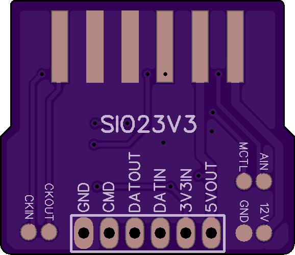
2
layer board of
1.16x1.00
inches
(29.36x25.35
mm).
Shared on
February 21st, 2017 20:43.
Description
The Atari SIO port runs at a 5V logic level. This board does down level shifting for connecting the Atari Data-In, Data-Out and Command lines to a microcontroller, Raspberry Pi or other device using logic levels less than 5V.
The board fits like an edge connector in between the two rows of pins in the Atari SIO port and is modeled after the Atari8Warez “Poor Mans SIO Cable”. The side labeled “SIO23V3” is the top/up side.
OSHPark boards are only 1.6mm thick which requires adding solder to the Atari SIO pads so they make contact with the pins. I don’t know exactly how much is needed, but it took several tries of adding more to get it just right.
So far, I have tested this board on my Atari 400 connected to an ESP-01 (esp8266, 3.3V). The Atari 400 5V output was able to keep the ESP-01 powered (thru a 3.3V voltage regulator) and connected to a bbs via telnet over Wifi using this modem emulator code.
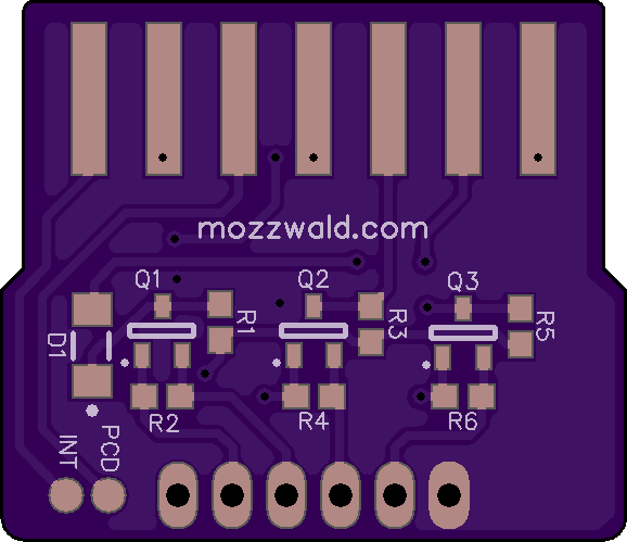
Part List
- D1: LL4150GS18 (or comparable)
- Q1-3: DMG2302U (or comparable)
- R1-R6: 10K 0603 5%
- 6 pin 0.1"/2.54mm Header (or directly soldered wires)
Pin Description
- GND: Ground
- CMD: Atari SIO Command Pin (level shifted)
- DATOUT: Atari SIO Data Out (to device RX, level shifted)
- DATIN: Atari SIO Data In (to device TX, level shifted)
- 3V3IN: Low voltage input (device logic level)
- 5VOUT: Atari 5V/Ready Output (can be used to as supply for low power microcontroller, current limit unknown)
Test Points/Pads
The remaining pins on the Atari SIO port are routed to test point pads on the board for experimenation. Keep in mind, these pads are directly connected to the Atari (no level shifting).
- CKIN: Clock In
- CKOUT: Clock Out
- MCTL: Motor Control
- AIN: Audio In
- GND: Ground
- 12V: +12V (Atari 400/800 only)
- INT: Interrupt
- PCD: Proceed
Zipit Z2 Breakout v2.0
by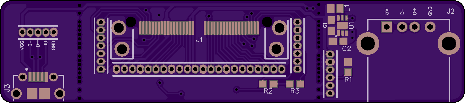
2
layer board of
2.96x0.66
inches
(75.11x16.69
mm).
Shared on
August 1st, 2016 22:18.
Zipit Z2 Breakout v2
Parts List
- C1, C2: 4.7uF 6.3V 0603 (C1608X5R0J475K080AB)
- L1: 1uH 0805 (LQM21PN1R0MC0D)
- U1: TI 5V Regulator (TPS61240DRVT)
- J1: Hirose to Zipit Connector (ST60X-36S)
- J2: USB Host Port (292303-1)
- J3: Amphenol FCI Micro USB Port (10118194-0001LF)
- R1: 10K ohm 0603 Resistors (Regulator Enable)
- R2, R3: 4.7k-10k ohm 0603 Resistors (I2C)
- 1.27mm Headers
Details
Both USB Ports are designed to be optionally broke off the middle section. Score the board with a blade on both sides down the line of holes and snap off the end. Each board when broken off can be used independently.
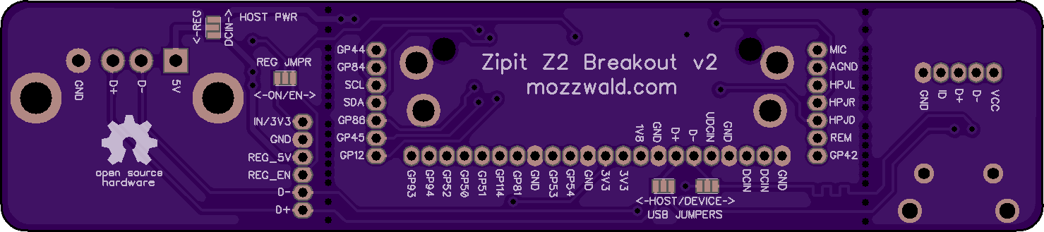
Main Zipit Board
This section of board contains the Hirose 36 pin connector, 1.27mm pitch headers, I2C resistors and “USB Jumpers”. The USB Jumpers allow connecting either the Micro USB (for device mode) or USB A (for host mode) port to the USB pins on the Zipit. The center pad of the jumper is connected to the Zipit. Bridge the center pad to the left or right pad with solder to set Host or Device mode.
USB-A Board
This section of board contains a USB A Port, 3.3V to 5V boost regulator, 1.27mm pitch header and jumper pads for the regulator and host power. When attached to the main Zipit board the “Host Pwr” Jumper sets which power is supplied to the port; DCIN from the Zipit or 5V from the regulator. The “Reg Jmpr” sets the regulator to be always “ON” or by toggling the “EN"able pin high (GPIO54 or via header).
Micro USB Board
This board contains a Micro USB port and 1.27mm pitch header. The VCC pin is connected to DCIN allowing you to power the Zipit via USB cable.
iPhone Battery Charger v2.2
by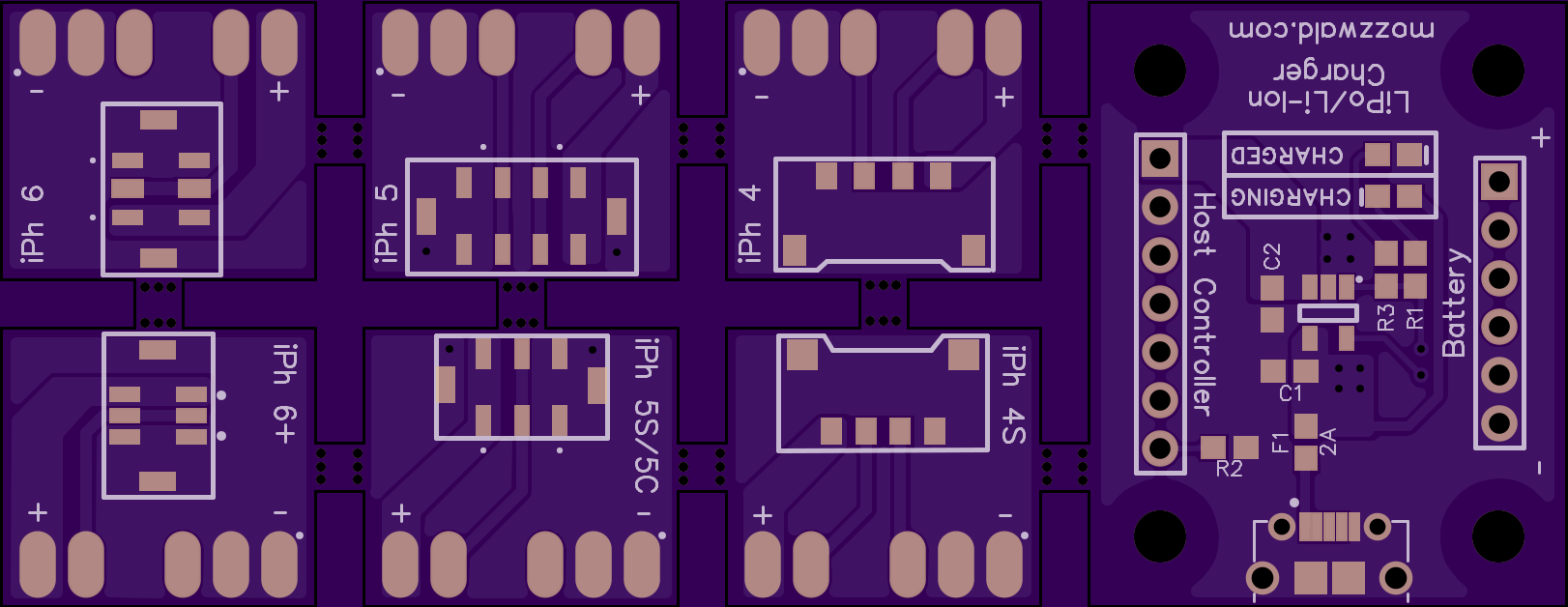
2
layer board of
3.24x1.26
inches
(82.40x31.90
mm).
Shared on
July 10th, 2016 14:56.
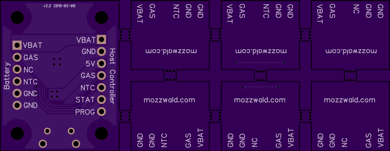
iPhone Battery Charger v2.2
This board is design to charge an iPhone 4, 4S, 5, 5S, 5C, 6, 6+ battery. The battery connectors are on separated sub-boards and only one can be connected to the main charging board at a time. Use 2.54mm male pins on the battery boards and a female socket on the main charging board. The battery boards are missing one pin to make the board ‘keyed’ so it can only plug in to the main board in one direction; this pin must be removed from the battery board header and it is recommended to add a plug to the female header on the main board.
The ‘Host Controller’ header allows connecting the charge board to a microcontroller for testing batteries. The iPhone batteries use TI Fuel gauge IC’s and communicate using the HDQ protocol. I have an example Arduino sketch that can be used to display some basic battery stats from the fuel gauge IC (GAS pin). The PROG and STAT pins are connected to the MCP73831 pins. For more info on these pins see the MCP73831 datasheet.
| RefDes | Component | Part # |
|---|---|---|
| C1 | 4.7uF 6.3V 0603 | - |
| C2 | 4.7uF 6.3V 0603 | - |
| F1 | 32VDC 2A Fuse 0603 | - |
| R1 | 1K ohm 0603 | - |
| R2 | 2K ohm 0603 | - |
| R3 | 1K ohm 0603 | - |
| U1 | MCP73831 SOT23-5 | MCP73831T-2DCI/OT |
| LEDCHGD | Green 0603 | - |
| LEDCHG | Orange 0603 | - |
| USB1 | FCI MicroUsb | 10118194-0001LF |
| Headers | 2.54mm / 0.1" | - |
| Header Plug (1) | - | 15-04-0292 |
| iPhone Conns | - | eBay |
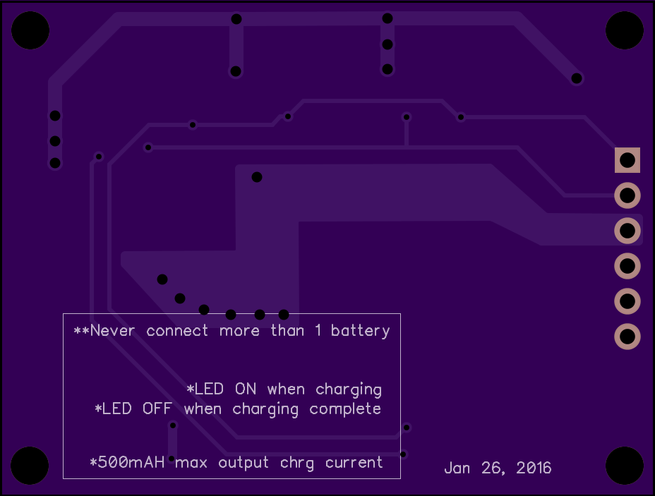
iPhone Battery Charger v1.1
by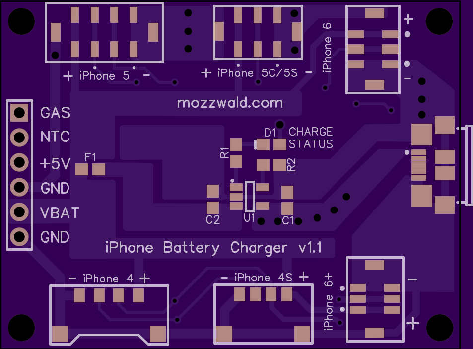
2
layer board of
1.86x1.41
inches
(47.14x35.71
mm).
Shared on
January 27th, 2016 01:09.
iPhone Battery Charger breakout using MCP73831
Zipit Z2 Breakout v1
by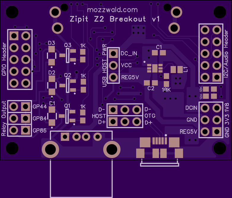
2
layer board of
1.96x1.36
inches
(49.68x34.44
mm).
Shared on
May 10th, 2015 21:13.
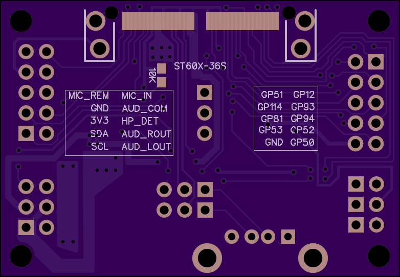
Zipit Z2 Breakout v1
Parts List
- C1, C2: 4.7uF 6.3V 0603 (C1608X5R0J475K080AB)
- L1: 1uH 0805 (LQM21PN1R0MC0D)
- U1: TI 5V Regulator (TPS61240DRVT)
- Q1, Q2, Q3: MMBT2222A
- D1, D2, D3: SM4004PL-TP
- Hirose to Zipit Connector: ST60X-36S
- USB Host Port: 292303-1
- Micro USB Port: ZX62R-B-5P
- 1K x 3: 1K ohm 0603 Resistors
- 10K x 4: 10K ohm 0603 Resistors
- 2x5 2.54mm pitch Header x2
- 2x3 2.54mm pitch Header x3
- 1x3 2.54mm pitch Header x1
- Jumper (Shunt) x3: 382811-8 (standard 2.54mm pitch type)