OSH Park
Arduino Due CAN Test
- You need to sign in or sign up before continuing.
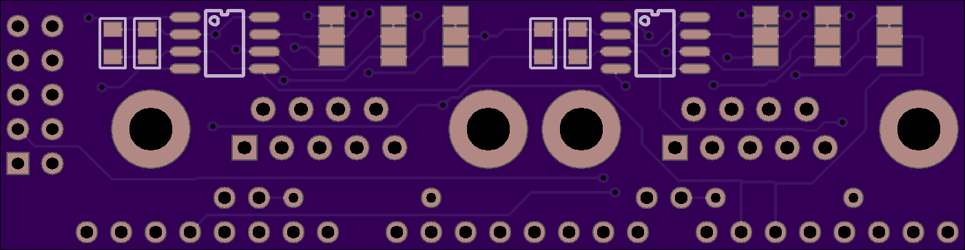
Arduino Due CAN Test
by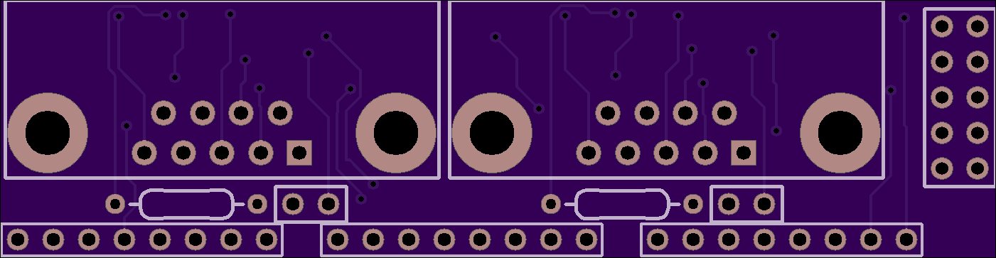
2
layer board of
2.80x0.73
inches
(71.17x18.47
mm).
Shared on
November 20th, 2013 13:14.
This circuit board attempts to implement this schematic: (by Palliser, not me… see the Arduino Forum link below for details)
http://forum.arduino.cc/index.php?topic=131096.msg1011501#msg1011501
The DB9M connectors are designed for this cable.
http://autocheckengine.com/products/obdii_cable_type_b.htm

Another pinout for CAN with DB9 is sometimes used (CANH & CANL on pins 7 & 2). Solder pads on the button side allow reconfiguring for the other pinout.
Recommended Components:
Qty   Digikey P/N       Description
---   -----------       -----------
 2    296-27991-1-ND    CAN transceiver
 2    445-7660-1-ND     Capacitor, 10uF, 805
 2    399-1170-1-ND     Capacitor, 0.1uF, 805
 2    609-4003-ND       DB9M connector
 2    CF14JT120RCT-ND   Resistor, 120 ohm
 2    3M9447-ND         Header, 2 pin
 2    3M9580-ND         Jumper