OSH Park
Shared projects
tinyTorch v1.1
by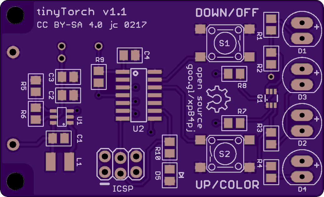
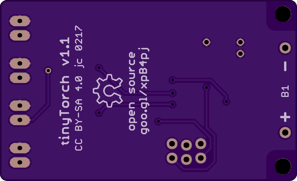
2
layer board of
2.07x1.26
inches
(52.50x32.00
mm).
Shared on
March 30th, 2017 15:02.
A small LED flashlight powered by an ATtiny84A
LTC2943
by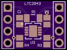
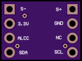
2
layer board of
0.57x0.43
inches
(14.38x10.80
mm).
Shared on
March 30th, 2017 14:45.
[Untested] LTC2943 Breakout
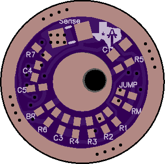
17mm V2 Texas Commander Tiny85
by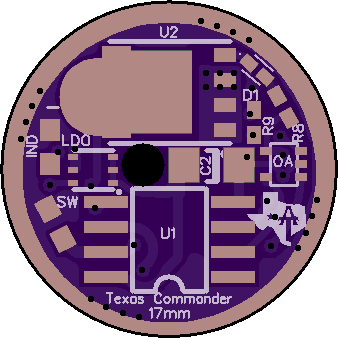
2
layer board of
0.68x0.68
inches
(17.15x17.15
mm).
Shared on
March 30th, 2017 14:17.
Ok, I don’t have time for my normal long post explaining every little detail of this driver. Plus with all the advancements coming down the line in driver tech I see bigger and better things coming out this year anyways.
Still this is a good concept and works great so it is worth posting it up.
Basically while this was not the goal, this is an open source LD-3 driver. The difference being that the LD-3 has a better 4 layer PCB and can handle a bit more heat then this driver. The features and basic setup are similar though. This driver also offers the ability to run bistro, which was the biggest reason for making it.
If you like the LD-3 firmware, just buy that and save yourself the time of building a driver by hand.
The credit design of the driver goes to DEL, he did all the technical design work, I just crammed it onto a 17mm driver and made his life harder by demanding every possible option be included. ^:)
So lets start off with the features of this driver:
It offers true constant current regulation without PWM It has a very low dropout voltage, which means it will maintain regulation as long as possible It is very low resistance, offering max power in turbo mode The regulated output can be overridden with a direct FET drive channel. Allowing for normal turbo modes like we are used to. It offers a moon mode and/or indictor LED channel if the firmware supports it. It can be used with either e-switch or clicky firmware It is setup for the new OTSM firmware that flintrock has been working on to remove all the OTC issues It has a large 1206 C2 cap for the OTSM
Now for the limits of the driver:
The short of it is that it gets hot and there is no effective way to cool it with low Vf LED’s. On older LED’s it should work fine.
The longer version is this drive being a linear driver means that it burns off all excess voltage as heat. When you boil it down, linear drivers are basically variable resistors (this applies equally to 7135’s the LD-3 ect). In this case that heat is produced in the FET and has to be dissipated in some way or things will start melting.
Due to the FET not having any way to thermally connect it to the body of the flashlight we are limited to passive cooling via the air and PCB. This is limited to around 2W of heat dissipation. If you fill the driver with thermal cube or pot the driver it could handle more but still 3W would be pushing things.
Now 2W is fine for pretty much all the “last gen” 3V LED’s. They will at most need about 1.5-2W dissipated due to the higher Vf. 6V LED’s could also ok if you avoided mode in the 30-70% range where the FET is hottest.
With modern low Vf LED’s things are very different. Even a single 219C could need as much as 4-5W of heat dissipated to maintain the correct output. Triples or 6v LED’s are even worse. It is simply too much for the FET to handle and it will overheat.
So if you are planning on using this driver, be sure you figure out how much heat it will have to dissipate. You can limit the regulated current to reduce the heat and then use the turbo mode with PWM for higher power outputs, this works fine even for low Vf LED’s but is also not that much of an upgrade over a normal FET+1.
Firmware options:
It is setup around the pinout of bistro. Bistro does work with it as is if you install an OTC on the SW pad. The flintrock version of bistro with OTSM should work on it as well but it is not tested.
Parts list:
The part list is included in an excel file in the oshpark download here : “Texas Commander 17mm download”:https://644db4de3505c40a0444-327723bce298e3ff5813fb42baeefbaa.ssl.cf1.rackcdn.com/07c9605dffeb0e71148658b2661c0b7c.zip
Here is a screen shot of that list, there is also a calculator to figure out the resistors needed for your desired current. This file was put together by DEL.
!{width:100%}http://i.imgur.com/VODkn32.png!:http://i.imgur.com/VODkn32.png
So now for the driver itself:
Here is the oshpark link : https://oshpark.com/shared_projects/e7beLCaV
It uses an opamp for the regulation circut. It gets a PWM signal through a DAC as the input and then regulated the output without PWM according to this input.
It has a separate channel for moon mode via a resistor, it will need firmware with voltage compensation to keep moon modes somewhat stable but you can also get ultra low moon modes.
Another channel is for the direct FET control for normal PWM control of the LED.
It has been tested by both me and DEL and appears to work great, it regulated the current fantastic. Just make sure you try to stay under ~2W of heat max, 1.5W is better. You can do this by lowering the amount of current it regulates and taking care of higher modes with PWM via the FET directly.
*Here is the schematic: *
!{width:50%}http://i.imgur.com/7N9wiVQ.jpg!:http://i.imgur.com/7N9wiVQ.jpg
Here is the driver mostly populated:
!{width:50%}http://i.imgur.com/J7L4pil.png!:http://i.imgur.com/J7L4pil.png !{width:50%}http://i.imgur.com/BQpbCfJ.png!:http://i.imgur.com/BQpbCfJ.png
Here is the driver empty:
!{width:50%}http://i.imgur.com/azvkfwB.png!:http://i.imgur.com/azvkfwB.png !{width:50%}http://i.imgur.com/azvkfwB.png!:http://i.imgur.com/azvkfwB.png
MD switchless Mod.zip
by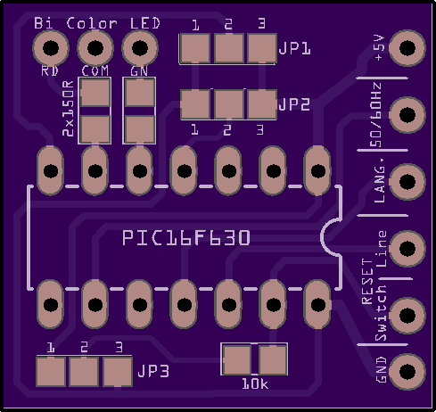
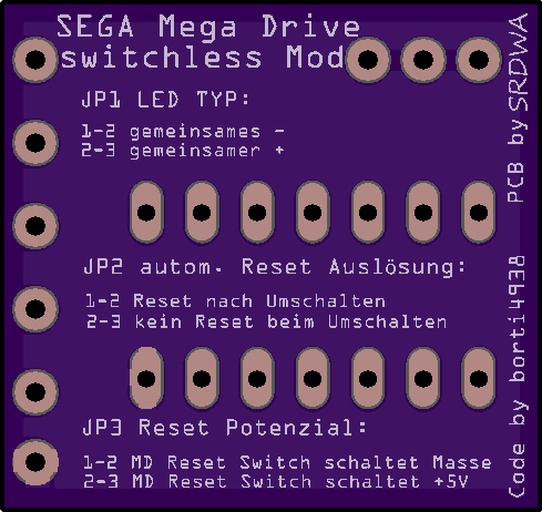
2
layer board of
0.98x0.93
inches
(24.84x23.49
mm).
Shared on
March 30th, 2017 08:19.
FR4133 Launchpad Prototype.kicad_pcb
by
2
layer board of
4.66x3.58
inches
(118.26x90.96
mm).
Shared on
March 30th, 2017 04:31.
Protoboard for Front Panel of The White Box. Pairs with TI Launchpads.