Welcome to OpenBuilds Community

Signup today and join in on the fun!

Sign Up

890KV OX RC spindle

Discussion in 'Other Builds' started by Robert Hummel, Jan 13, 2014.
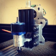
  1. Robert Hummel

    Robert Hummel Custom Builder Staff Member Builder

    Ty bud! :D
    It's really solid, I have 30mm M5s holding it.
    The bearing plate is going to sandwich between the 2.
    Just hope it comes together the way I have it planed out in the head :rolleyes:
  2. kram242

    kram242 OpenBuilds Team Staff Member Builder

    I think its build like a tank and I would think thats a good thing for a spindle.
    3-30mm M5 its not going anywhere! :)
  3. Tweakie

    Tweakie OpenBuilds Team Staff Member Builder

    Excellent project build Robert - that is going to be a great little spindle. :thumbsup:
    Is there any form of locking between the rotor and the shaft or is it just a press fit ?

    Tweakie.
  4. Robert Hummel

    Robert Hummel Custom Builder Staff Member Builder

    Ty
    Yes there are 2 m3 set screws in the motor housing, so them along with the snug press fit I don't see any issues.
  5. Yusuf Tumer

    Yusuf Tumer Well-Known Builder

    Are these types of spindles significantly quieter than a trim router? Also, would it be possible to mill Aluminium with this type of spindle if you made light passes?
  6. Robert Hummel

    Robert Hummel Custom Builder Staff Member Builder

    To your first question I'm not sure as I have never used a trim router, to the second question yes, I have milled 3/8 plate @1/64 passes :)
  7. Yusuf Tumer

    Yusuf Tumer Well-Known Builder

    Thanks Robert. Your build looks great. I might replicate it for my OX eventually.

    By trim router I meant a hand held router similar to the one kram uses :)
  8. Robert Hummel

    Robert Hummel Custom Builder Staff Member Builder

    Aww ok lol
    I would say just as hard on the ears maybe a little less
  9. DSardano

    DSardano Well-Known Builder

    Rob - I noticed the spacer\mount was revised from the original rounded two hole config to a more "T" like three holed config. Are you able to post that file up to the site? Thanks
  10. Robert Hummel

    Robert Hummel Custom Builder Staff Member Builder

    Yep, I will do it tonight after work.
    Ment to do it a while ago but never had a chance as I spend most of my free time now milling plates

    BTW all the files have bin updated to make for a more round and clean setup.
    The original files had a lot less segments
  11. DSardano

    DSardano Well-Known Builder

    That's awesome; thanks for the update. Any chance you could let me know the pricing on the OX Plates and the Garolite Spacers for NEMA 23's ?
  12. Robert Hummel

    Robert Hummel Custom Builder Staff Member Builder

    I do not mill Garolite as it's hard for me to get and Canada has marked it as un-safe to mill.
    The spacers for my nema23 motors are made from acrylic or HDPE
    As for OX plates I am only doing 4 main plate sets with belt end clips/hardware, the waiting time is around two weeks for a set to be made"can only mill so fast lol"
    Right now there are 2 sets in line.
    Pricing is figured out at time of confirmation a set is available due to shipping costs.
    Start a conversation to get cost as I do not post publicly out of respect to the forum :)
  13. DSardano

    DSardano Well-Known Builder

    Robert - completely understand and agree; no disrespect for the forum intended. Regarding the Garolite, the HDPE is absolutely fine. If possible please place me "third in line" and if your agreeable please reach to me off-forum at sardanod@gmail.com
    once again thanks.
    Robert Hummel likes this.
  14. DSardano

    DSardano Well-Known Builder

    BTW, thanks for updating the Spindle files; looks good.
  15. Robert Hummel

    Robert Hummel Custom Builder Staff Member Builder

    No prob :)
  16. Jestah

    Jestah Journeyman Builder

    Face palm moment.... I ordered a 10mm shaft chuck not an 8mm.... NOOOOooOOOoooO!!!!! I am not one part short form being able to spin this spindle up. So close its killing me! The good news was I did notice a few days after placing the first order so expect the right one any day now. Phew :)

    I decided while I wait for the post man I would try out the motor and get it talking to mach3.... I have found this is far harder than I expected.

    I have a 100A ESC (swy-wing SW-100A) that looks like it takes a PWM signal into but as it came with no information and the seller is not keen to help so I am a little stuck.

    What recommendations do you guys have for getting speed control to work? Manual for now is ok by me but I would like to move control over to mach3 in the near future

    I am just about to try to get my head around the sketch posted by @The Dude to see if that may work for me.

    @Robert Hummel what was that little interface card you use in your demo clip?
  17. Robert Hummel

    Robert Hummel Custom Builder Staff Member Builder

    It's a servo motor tester made in house.
    I have not tried myself to get mach3 to control the speed but I'm sure there is a way, now u got me thinking lol

    What the ESC needs to run is a modified version of a PWM square wave. Its a 1-2ms pulse every 20ms at 5v. So 1-2ms pulse @ 50Hz (0 rpm @ 1ms, full rpm @ 2ms).
  18. Jestah

    Jestah Journeyman Builder

    I was planning on using a G540 for a small cnc so have 0-10v out that I could use .... Would it possible to splice this into where the adjustment pot is for the servo tester circuits I have found if I set the 540 to drop the output down to 0-5v?
  19. Jestah

    Jestah Journeyman Builder

    also if any one has time would they mind explaining how to choose a suitable power supply for the spindle.

    Swy-wing SW-100A
    Constant Current: 100A
    Max Current: 110A
    BEC output: 5A
    Input Volt: 6 - 22.2V (2-6 LIPO / 4 - 20 NIMH)
    Low-Voltage Cutoff: Auto detect and set

    I have a 15v 23A supply in a 3d printer that my gut says can supply enough current but I am unsure exactly how to do the calculations to make sure I am not way under or over matched with a C5045 KV890 Outrunner

    Also would a small VFD be able to drive the motor directly?
  20. Robert Hummel

    Robert Hummel Custom Builder Staff Member Builder

    A 12-14 vdc power supply @10 amp rating will be enough

    As for the VFD they are designed to work with AC induction motors.
    These are completely different than the brushless DC motor.
    Closest AC motor would be a 3 phase permanent magnet synchronous motor.

    The main differences are the means of torque generation.

    Induction motors develop torque based on "slip" which is the difference between stator field rotation and rotor mechanical rotation.

    BLDC motors never "slip" in normal operation.

    AC synchronous motors generate torque based on the phase angle between the rotating field and the rotor.
    No load, 0° phase lag. Max load 90° phase lag.

    BLDC motors run at more or less constant phase angle (timing).
    Torque is a result of the rotating fields magnitude which is proportional to current.
  21. Robert Hummel

    Robert Hummel Custom Builder Staff Member Builder

    Try checking this out and if you need help to make the pcb I have the material on hand.
    If anyone that feels they can program a attiny to do this I again have the means just not the programing skills.

    I would like to have this myself for sure so anyone wanting to try and replacate this device I'm in :)


    http://www.rcgroups.com/forums/showthread.php?t=1529715
  22. oni305

    oni305 Veteran Builder

    I havent Mach3 (nor a cnc yet :p) but i think it not to difficult to create a little board to generate the PWM

    something like this
    sad.png

    it can also function as a servo tester relacing the RC filter whit a pontetimeter
  23. Robert Hummel

    Robert Hummel Custom Builder Staff Member Builder

    Sweet!
    I will try and design a pcb :)
  24. Robert Hummel

    Robert Hummel Custom Builder Staff Member Builder

    You wouldn't happen to have any code to make that circuit work would ya :p
    If I'm right it would work by converting the v ref from mach3 0-10 vdc and convert that into an output scale from 1-2ms.
    So 1 vdc = 1.1 ms pulse and so on

    Edit!
    The 0-10 vdc has to be divided to be acceptable for the attiny so the scale would differ ;)
    .5 vdc = 1.1ms pulse
  25. oni305

    oni305 Veteran Builder

    No, i haven't any code...(yet) i'have design that schematics with a "random" attiny only for the concept..

    This schematics trasform a pwm to an analog tension 0-5v, read the value and generate a new pwm

    If you give me some specification of the output which mach3 gave, i can design a more accurate circuit!
  26. Tweakie

    Tweakie OpenBuilds Team Staff Member Builder

    Just thinking out loud...

    The Mach3 PWM output will have an amplitude that matches the TTL standard used by the parallel port - some will be to the older 5 Volt standard and the newer parallel ports will be to the 3.3 Volt standard.
    This may add a slight complication to the analog sampling method if a PWM driven speed controller is to be universal between different PC's.

    Not an obstacle that can't be easily overcome but you may want to take it into consideration at this stage. ;)

    Tweakie.
    Robert Hummel likes this.
  27. Jestah

    Jestah Journeyman Builder

    Wow... I have just put one together and I'm impressed! The work you did @Robert Hummel is really top notch! The unit feels like its really stiff for the total overall weight and power. Thanks a bunch !!!

    After a light test assembly I am pondering how to lock the collet chuck to the motor. I could drill a little dent into the collet shaft to take the set screw but is this enough to stop the spindle as the back part of my motor seems to be quite lose?

    I was also wondering should the last ring with the top bearing be placed bearing to motor or the other way around?

    In a skateboard wheel it is really important to run spacers between bearings inside the wheels.... Wheels drift more predictably, grip longer and wear evenly. Would this spindle also benefit from packing out any "blank" space on the shaft?

    OR am I over thinking this just as someone who is one speed controller away from being able to cut would?
  28. Robert Hummel

    Robert Hummel Custom Builder Staff Member Builder

    I don't
    I would say your over thinking it but there is always room for improvement ;)
    The bearings in the RC motor should take care of the slop your thinking of and the skate bearings really just act as a guide and add strength.

    When you say your motor is loose, is it just press fit?
    My motors come with grub screws to lock it on the shaft.

    The last skate bearing faces down to press it in place when everything screws together if that makes sence
    And I also lightly pack the empty space with lithium bearing grease :)
    Jestah likes this.
  29. Jestah

    Jestah Journeyman Builder

    ah overthinking.... its what I do!

    There is a set screw in the motor housing (the part that spins) but this part is quite loose on the shaft and I was worried that the grub screw was not going to bite into the stock shaft to provide a good grip. I will mark the spot and then drill in a little indent to help lock the grub screw but this still loads the motor bearings with drilling force.

    As you say the force should be fairly minimal but if it can be easily eliminated we may get a even stiffer spindle.

    For me putting spacers between my longboard wheel bearings when I am skating down a hill at 90+KM and cornering at high speeds (high loading situations) the feel and smoothness is night and day. Surely if a bit of 8mm ID tube just the right length would be a very cheap and worthwhile add on?

    I feel that once the two skate bearings are connected with a solid tube to space them properly apart I could also add a locking coller to the stack so the drilling force is isolated to the skate bearings and then the setscrew on the motor would only be there to stop it spinning against the shaft.

    I will track something suitable down next week. If it goes well Ill let you know but for now I will just setup without as its very stiff even without the spacers!

    Time to stop overthinking and get it working so found the image for a servo pulser you posted a while back, is that what you are using as I think I have most of the parts already.


    [​IMG]
  30. Robert Hummel

    Robert Hummel Custom Builder Staff Member Builder

    Yes that is the circuit I'd built and it does the job :)
    I will be firing up mine soon, just a matter of getting time away from the mill lol

Share This Page