
OSH Park
Profile for pfriedel
Shared projects
WS2812 and Beeper 24mm wide
by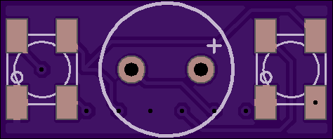
2
layer board of
0.95x0.39
inches
(24.00x10.01
mm).
Shared on
December 20th, 2016 22:38.
beep beep beepity beep
Is 35mm too wide? I’m sure it is. Here’s one that’s only 24mm. As small as I can make a pair of 5050’s and a beeper. needs a special beeper, too!
https://www.digikey.com/product-detail/en/pui-audio-inc/AI-1027-TWT-5V-2-R/668-1454-ND/5011389
Go nuts.
lights and buzzers
by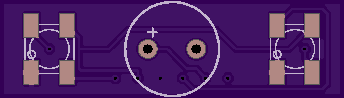

2
layer board of
1.38x0.39
inches
(35.00x10.01
mm).
Shared on
September 8th, 2016 22:29.
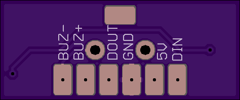
Now with data out. Only 35mm wide, for really tight builds. The beeper is this:
https://www.digikey.com/product-detail/en/pui-audio-inc/AI-1027-TWT-5V-2-R/668-1454-ND/5011389
Although I suspect any 9.6mm diameter active buzzer would work. Notably, that rules out most eBay options which are 12x9.6 or thereabouts.
lights and buzzers
by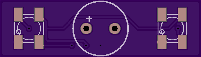

2
layer board of
1.38x0.39
inches
(35.00x10.01
mm).
Shared on
July 14th, 2016 13:42.
gimme a beep!
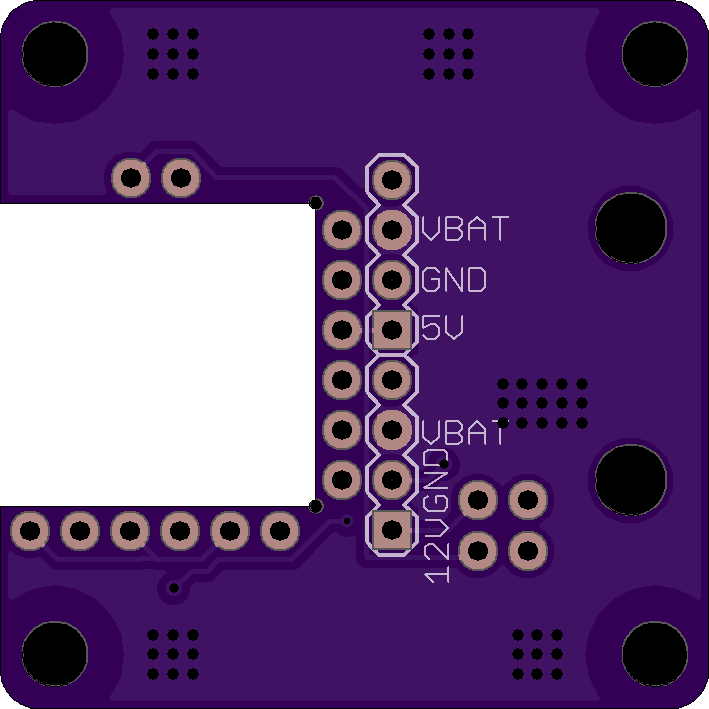
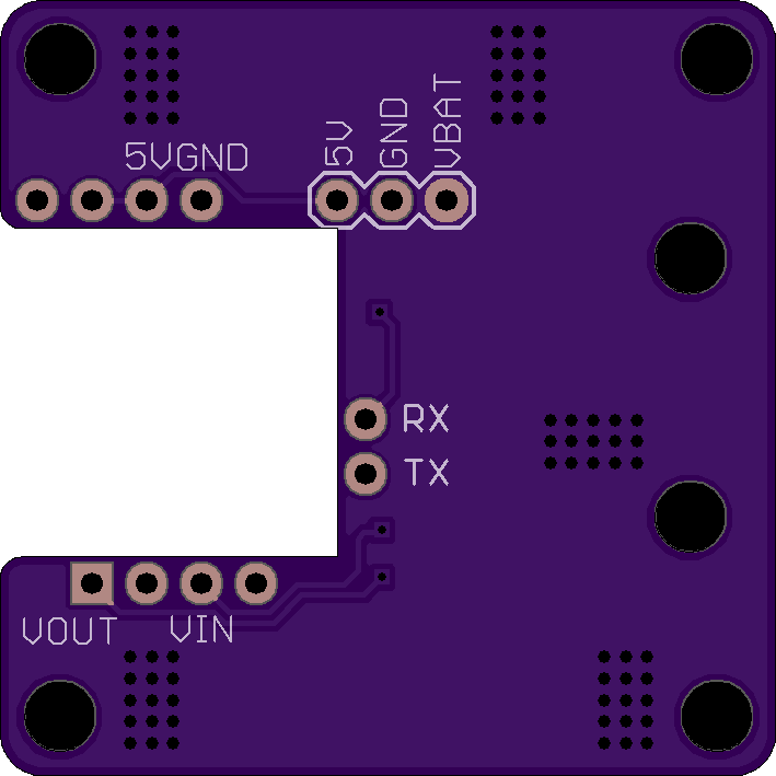
Micro MinimOSD PDB v2
by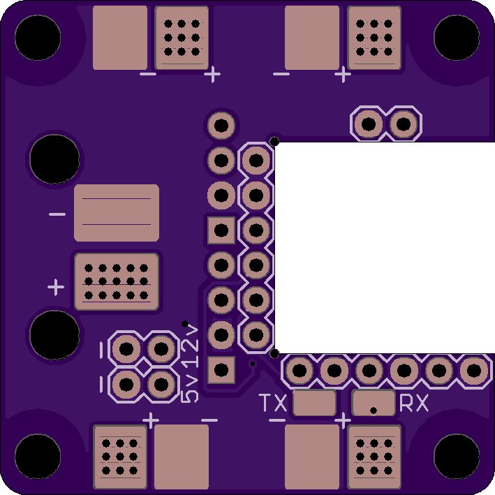
2
layer board of
1.42x1.42
inches
(36.02x36.02
mm).
Shared on
May 29th, 2016 20:54.
Better sizing! Fewer Pads! Less chance starting a damn fire if you know what I mean
Micro MinimOSD PDB
by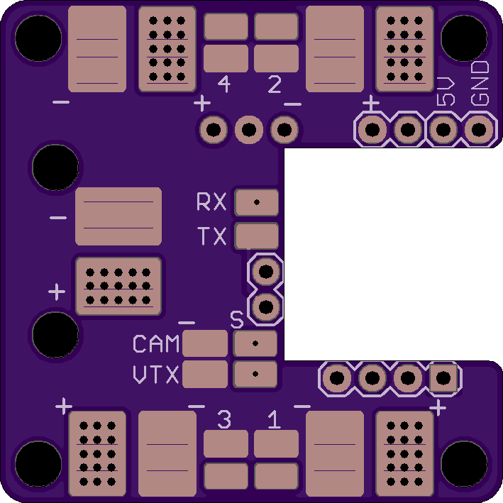
2
layer board of
1.42x1.42
inches
(36.02x36.02
mm).
Shared on
May 5th, 2016 16:38.
Note: No clearance on standoffs is an almost guaranteed short circuit with metal standoffs. And the minim cutout is undersized. And why not have a 12v reg, since there’s space. Anyway, don’t use.
I like an OSD, but I hate wiring it. Put the Pololu reg on top or beneath the board. Fundamentally just a respin of the Atom PCB, but with bigger tracks for the power leads because the Atom PCB doesn’t look like it’d stand up to a constant 5A per motor load.
The pads are mostly laid out to be as directly wired for a SN20a as possible, but the pads for motor #1 are reversed to provide better current handling for the negative rail.
There are ground and signal “pads” near the power pads for jumping from the ESC to a second wire for running up to the FC.
Warning: Untested. Order at your own risk.