Welcome to OpenBuilds Community

Signup today and join in on the fun!

Sign Up

Routy CNC Router (V-Slot Belt & Pinion)

Discussion in 'CNC Mills/Routers' started by kram242, Nov 11, 2013.
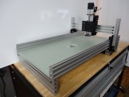
  1. kram242

    kram242 OpenBuilds Team Staff Member Builder

    Well said David :thumbsup: Thanks for these tips
  2. Ceiling Cat

    Ceiling Cat Journeyman Builder

    Some of the information required by the calculator that you posted is confusing to me. For instance what is chip load per tooth? How do you find it out? What units is it measured in? I didn't see any surface feed rate for acrylic listed there on that site but maybe I missed it. Could you give an example of how to use this tool for us newbs? Say for acrylic for example or choose one of the more common materials that new people would be working with like wood and walk us through and example? I would be happy to use calculators if I knew what to put there or where I could find the information.
    JustinTime likes this.
  3. The Dude

    The Dude Veteran Builder

    Who says we're guessing? The scientific method is what we're doing. We conduct experiments, publish our findings, and then reproduce the work of others to verify/debunk.

    As for oil, yeah it's probably not environmentally friendly to use petroleum products. I'm switching to vegetable oil. Something which evaporates, like ethanol, would help with sucking the chips up without gumming up the dust boot. I'm wary of anybody selling special lubricants... repackaged vegetable oil at a premium price? This is pretty common nowadays. Just the other day someone tried to sell me fertilizer(poop) and they claimed that it was somehow magically better than other poop but they can't explain why or show me any evidence or ingredients.
  4. The Dude

    The Dude Veteran Builder

    The acrylic is on another chart. It says to use 200mm/min @50% plunge rate and 0.0762mm cut depth. That was for a 1/4"(6.35mm) bit. My spindle runs at 10,680 rpm. I cut through 1/2"(12.7mm) acrylic and aluminium with those settings. The charts are good starting point.

    The surface speed(surface feet per minute or SFM) is a property of the bit you are using. The manufacturer tells you this. It's like a max rating for the material and shape of the bit.

    RPM = SFM x 3.82 / tool diameter
    My bit manufacturer only gave me the max RPM of the bit as 18000 so:
    SFM = .262 X RPM X Diameter of tool
    So for me, my SFM = 98.23428

    So according to the online calculator my RPM should be 18014RPM max. But my manufacturer already told me that, haha.

    I'm just guessing but # teeth = # of flutes. Chip load is the thickness of the material being removed(e.g. plunge depth). So like if you're spinning a bit with 2 teeth, it removes material twice on each revolution. So it could go faster than a bit with one tooth. SO in my case, I have 2 teeth and plunge depth of 0.0764mm(e.g. chip load = 0.0382mm = 0.001504in) so the online calculator says my feed rate should be 54.19 in/min = 1376.4 mm/min. Note: These are all based on maximum values for the bit and bear no corrections for the material hardness, flexing gantry, flexing spindle mount, etc that happens on my machine. So yeah I'm running mine at about 20% of what it could potentially do. I may increase the speeds 100% one my spindle mount is completed.

    I can see why this is confusing. There are many variables that go into deciding the settings for a CNC machine. My approach has been to use standardized bits that everyone is using and ask around when in doubt. The charts are a good launch-pad but ideally you should be performing the calculations based on the variables specific to your setup.
    Last edited: Mar 19, 2014
    Ceiling Cat likes this.
  5. Ceiling Cat

    Ceiling Cat Journeyman Builder

    Thanks, I was way off in my assumptions about that calculator. That makes a lot more sense now. I had played around with calculators before but got some questionable values so I just stopped using them. I'll give them another shot now.
  6. David the swarfer

    David the swarfer OpenBuilds Team Staff Member Builder

    chip load per tooth is 'how deep each tooth cuts' and is recommended by the tool maker. normally in the range of 0.002 to 0.008 inches for woodworking carbide bits, but again, look it up on the tool makers web site.
    inches, millimeters, just whatever is common wherever the manufacturer lives.
    SFM is the critical number, and comes primarily from the material being cut, and then the type of cutter being used. (and not primarily from the bit as the dude implies above) . This number tells you how fast each tooth can be moved through the material to get a good cut, too slow is as bad as too fast!

    The bit can be made from various metals, and coated with various other things.
    High Carbon steel is the cheapest, as in cheap twist drills. Get them too hot and they get soft, and this limits their cut rate. You can buy blank material from which to make custom cutters, and heat treat it at home with an LPG torch or stove. see http://www.warfer.co.za/lathe for examples.

    High Speed Steel or HSS has additives that make it heat resistant. This caused a major stir when it was revealed at a major tool show in about 1930, they ran it a half inch deep in steel with the tool glowing dull red and it stayed hard and sharp and still cut. Very tricky to heat treat, but so much easier to grind to shape at home (but don't get it red hot and dip it in water, it will crack).
    This is often coated with Titanium Nitride, the yellow one, which makes the surface more slippery to prevent galling.

    Tungsten carbides are even harder, and hence more brittle so are unsuitable for interrupted cuts in hard materials as the shock loads cause cracking. This is most commonly seen as solid endmills, brazed inserts, or replaceable inserts. You need special grinding wheels to sharpen this stuff. Recommended for cutting glass filled nylon and other abrasive materials.

    surface feed rate for acrylic should really be had from the acrylic manufacturer.

    Tool bits are made with different angles to suite cutting different materials even though the bit itself is made from essentially the same metal. This is where the big differences come in. A bit for metal has completely wrong angles for plastics (and a steel cutting bit has the wrong angels for brass, etc), hence my previous advice to find aluminum and plastic specific tools, they really do make a big difference, especially on our lighter 'flexible' CNC machines.

    So, an example calculation
    I have a 2 flute carbide router bit, 6.35mm (1/4") diameter and I want to cut some aluminum.
    so I put in 1/4" for tool diameter and check the chart for SFM which says
    ALUMINUM ALLOYS 1200+ FT./MIN.

    for uncoated carbide, so I put in 1200 and press the calculate button,
    This gives me 18335 RPM as a minimum speed for the router. At this speed, each tooth will be going past the material at 1200 feet per minute at this tools diameter. A smaller tool would have to run faster, a larger one slower.

    Now, I put in 2 for 'no of teeth' and 0.002" for chip load per tooth, starting at the low end because I have a wobbly machine.
    This gives 73.34 inches per minute feed rate at this RPM. You can use 73 or 74 depending on your machine stiffness.

    So to sum up, the material and tool bit material give the surface speed that gives efficient cutting for that material, the SFM.
    The bit diameter and SFM give the RPM
    The RPM and 'chip load per tooth' = 'depth of cut per flute' give feed rate.

    Note that I used 2 low end values above, 1200 is a starting point for SFM in ali, depending on the specific alloy, and the type of coolant, and the shape of the toolbit, and the strength of the machine, you can go a lot faster if your spindle can get the rpm.
    0.002 is a low chip load, 2 thousands is not a lot to cut off and in production (where speed is king) you'd be looking more at 0.005 to 0.015 at higher SFM. They make 100000rpm spindles or a reason (-:

    An example of high speed aluminum cutting with good solid carbide cutters, ethanol coolant (not lubricant).

    I'm not saying our home shop machine can do this, that Datron machine is big and heavy and very stiff compared to a Routy. I'm saying that this is the result of doing the science properly. We don't need to experiment because it has all been done before.

    Note: if your spindle cannot get to 18000rpm you need to insert the speed it CAN do and then do the feed rate calculation because chip load is critical to surface finish, though too low a SFM will give poor results too.
    Ceiling Cat likes this.
  7. David the swarfer

    David the swarfer OpenBuilds Team Staff Member Builder

    yes
    no.
    chip load is how much each tooth cuts off as it passes, and is governed by the rpm and feed rate.
    'plunge depth' is not the same thing, this is how deep you are cutting, usually expressed in multiples of the bit diameter, as in 1/4D or 1D for once piece bits, and given by the maker for inserts since their edges are highly specialized.
    (plunge depth is not the right term but I just cannot think of it now)
  8. David the swarfer

    David the swarfer OpenBuilds Team Staff Member Builder

    I do :)
    environmentally friendly or not, it has nothing to do with whether or not it is the correct cutting coolant for the material being cut. We want to be careful to spread correct information here don't we?

    kerosene and ethanol are the correct coolants for aluminum unless you want to purchase one of the specialized products.
    any kind of lubricating oil is the WRONG THING for cutting.

    vegetable oil might work, but I've never seen it mentioned as a cutting fluid, despite years of actually cutting metal with a screw cutting lathe, and participating in forums and email lists, and reading magazines like 'Model Engineers Workshop'.
    for cutting steels, chicken fat, lard etc work very well if you want to avoid pumped coolants which are 95% water anyway, being an emulsion of a little of the right kind of oil, and water. why avoid pumped coolants? makes a mess, and it goes rotten in your machine.

    I have found bees wax to be very effective on all hard materials, just rub it on before each cut in the case of rotary tools, and just rub it on the saw blade now and then in the case of hacksaws. Using this I can cut through a 60x60mm block of steel in under 20 minutes, by hand. candle wax works well too, I use it when I cannot find my lump of beeswax. (and thinking about it, candle wax is really 'paraffin wax', and kerosene is part of the paraffin family)
  9. kram242

    kram242 OpenBuilds Team Staff Member Builder

    Great info David thanks and I really like the idea of the bees wax. :thumbsup: Thank you
  10. Ceiling Cat

    Ceiling Cat Journeyman Builder

    Wow lots of info there thanks for the example. So I guess my biggest problem currently... well besides for using the wrong bit is that I have no idea what my dremel tool spins at. There is a variable speed setting on it and I can adjust the speed but I have no idea how fast the thing actually goes. It could be 15000 rpm or it could be 5000 rpm. The is no indication on my tool so really I have no clue. Anyone know of any good tricks to find out / measure what your max RPM is on your tool?
  11. The Dude

    The Dude Veteran Builder

    I tried the vegetable oil and it works similar to 80w oil but is much thinner and doesn't stink as much. I'll give the beeswax a go next time and let you all know. One drawback to oils is that they bind the chips in place and you have to keep scraping out the lumps of oil+chips to keep the cutter from recutting them in deep cutouts.

    What we're doing here is original work. It's different from DIY cnc. It's like reinventing the wheel to have spokes rather than solid wheels. Instead of paywalled journals and fancy academic titles, we have open builds and open forums. Sometimes that means putting your best guess out there and then humbly accepting feedback. Some of the key differences in what we're doing are as follows:
    1. Low cost: $400 vs $4000
    2. Newer materials: Extruded aluminum, garolite, 3D printed parts, etc
    3. Libre and Gratis: free as in free beer and also free as in freedom
    4. Boot-strappable: No kit required, no cnc machine required, etc
    5. Community driven: We have the same thing as a company with 1000 employees because it's a large community of volunteers spanning all walks of life. Relying on one another makes progress possible that can't be done alone.

    Also, thanks for correcting my info. As you may know, I'm not an expert on machining and have had no formal CNC training. I'm just a physicist who worked in sys admin until the H1B invasion and then became a farmer and beekeeper(way cooler BTW). Anyway, from what I've seen, degrees/training/etc don't mean jack these days. The heavy hitters in machining are probably something similar to what we call script kiddies in hacking. They can follow a script but ask them to build a cnc machine from the ground up and they can't do it. That's probably why all those things in the videos looks like something from 1960, because that was when they were designed. The companies have survived because they were the only game in town for 50 years. I'm surprised they're not still using vacuum tube transistors, haha.

    So now it's a new time. We have lots of advancements that make CNC a whole new ball of wax. New materials, new knowledge, new computers, etc. But where are the ivory tower scientists to lead the way? Where are the almighty job creators? Anyone? Bueller? As far as I know, some kid in his mom's basement lead the development of 3D printing. Some dude in an apartment who works at McDonalds is leading the development of CNC.

    Anyway, that's just like my opinion man.
  12. The Dude

    The Dude Veteran Builder

    Some places sell handheld rpm meters too. You could attach a plastic disc with slots cut out of it and then pass the slots through an optical switch to count the rpms digitally.
    Last edited by a moderator: Mar 29, 2014
  13. Ceiling Cat

    Ceiling Cat Journeyman Builder

    I found one of these online. I'm kinda howto-ed out so I just bought it. Was only 15 bucks. http://www.rakuten.com/prod/new-non...e&adid=18172&gclid=CO3TnOSGpb0CFYyhOgodwQYAiA
  14. Rick 2.0

    Rick 2.0 Journeyman Builder

    I have that model and it works fairly well. What the photo doesn't show is the adhesive backed reflective strips provided that you cut to length and apply to whatever you need to measure. Not sure how well they will stick to high speed bits. Measured my dremel speeds all the way up by grasping the reflector in the chuck slots.
  15. David the swarfer

    David the swarfer OpenBuilds Team Staff Member Builder

    Radio control stores will have RPM meters for measuring prop rpm, they should be good to about 30000 rpm.
    what you will need is a short flat blade (icecream stick?) to form a 2 bladed prop that doesn't slow the dremel down, or 2 bits of black, 2 bits of white tape spaced around the chuck to give the same effect as a 2 bladed prop.

    Under AC powered lights you may have trouble getting a reading. What I do in my workshop is point an ordinary battery torch through the prop, at the RPM sensor. This overrides the flickering from the fluorescent lights and gives a stable reading.
  16. Ceiling Cat

    Ceiling Cat Journeyman Builder

    I just had the pleasure of using a 1/8th in. single flute upcut O bit you linked. WoW! This thing is well worth the cash and it is a night and day difference from my previous bit. I will try and post some pics of how everything turned out tomorrow for all to see. The acrylic is being cut beautifully with very clean edges. Thanks again @kram242 for the link on the bit.

    The RPM meter hasn't arrived yet but couldn't wait to get started. I used @The Dude 's settings for acrylic which is probably too conservative with the new bit I'm using. On my next cuts I will get some readings and do the math (use speed/feed tool) to really dial in the parameters for acrylic. I think I can probably go a lot faster with this new bit.
    David the swarfer likes this.
  17. kram242

    kram242 OpenBuilds Team Staff Member Builder

    No problem glad to hear you found it useful and your getting great cuts :thumbsup:
  18. Ceiling Cat

    Ceiling Cat Journeyman Builder

    Here are some photos of the results with the bit in case any want to see. The circle didn't come out too well because I was having troubles with the Y axis again. Should be good again now though, I kept having strange issues with one of the motors on the Y not wanting to work while moving -Y but was ok moving +Y.

    Going to try and recut the circle in hopes I can salvage the part. I will use one of the plunges I drilled earlier to line this up again for another attempt. Just curious but does anyone else drill a hole in their material right from the start to use that for alignment if they have to stop a cut? Or is it just me? I find it useful to do that so I can line everything back up again in case something goes wrong. Is there a better way to do this sort of thing? I saw http://openbuilds.com/builds/tool-position-setting-part-iii.490/ and would like to do that but I'm afraid I'm using GrblController so unless I add the code myself it may be hard to do. Would anyone out there like to have this capability added to GrblController?

    Attached Files:

  19. kram242

    kram242 OpenBuilds Team Staff Member Builder

    Thanks for the pics looks good
    This may be the case with the controller or even the belt tighter on one side then the other. My circles could be better as well and I think I need to tweak the belt.
    I do, thats what I use as my zero
    You can also use it for bit changes and for multiple codes on the same part.
  20. Rick 2.0

    Rick 2.0 Journeyman Builder

    If you'd like to save yourself the trouble of drilling screw holes for alignment, drill some peg holes in the spoils board. Set the material against the pegs, clamp it down, and then pull the pegs. While 3 pegs should do it (1 at the side, 2 across the end), having the machine drill a row of end holes at 6" centers across the end will not only set you up for whatever size material you put down, it will also guarantee squareness to the machine.
    Ceiling Cat and kram242 like this.
  21. Tweakie

    Tweakie OpenBuilds Team Staff Member Builder

    Excellent tip @Rick 2.0 :thumbsup:

    Tweakie.
  22. The Dude

    The Dude Veteran Builder

    This doesn't work when the machine slips during a cut. You have to manually touch off the workpiece again to resume. A tool-mark helps make this possible and an automatic tool positioner is even better. I suppose you could write down the offset of the workpiece from the home position when starting a job and then if it slips just rehome it and set the offset.
  23. The Dude

    The Dude Veteran Builder

    The photos show what looks like a timing issue. I had the same kinds of cuts on acrylic. Try slowing down the timing when changing directions. On LinuxCNC it's called "Direction Hold". There is also a rising edge and falling edge to each signal and getting them wrong can produce a missed step "only on -Y". If you're board is using rising edge then maybe changing the "Direction Setup" timing would fix it. read all about it here http://cockrum.net/cnc.html

    [​IMG]
  24. Rick 2.0

    Rick 2.0 Journeyman Builder

    While a tool-mark can guarantee the work is back in the same location, it cannot guarantee that the piece is not rotated slightly. For that you need 2 tool-marks and you will have to carefully manipulate the material until both are spot on (if your software cannot calculate the error and accommodate it). With pegs, the work goes quickly and easily back to its original location and orientation. And as the starting corner will always be in the same location, resetting the machine gets that much easier.
  25. The Dude

    The Dude Veteran Builder

    I agree and thanks for the info. I saw a technique for doing 2-sided PCBs which uses the same principle. With PCBs it's even more critical to get a square piece and flip it over perfectly. Actually this technique can apply to any material giving the possibility of machining 2 sides.
  26. Ceiling Cat

    Ceiling Cat Journeyman Builder

    I tried to re-cut tonight I aligned the part spot on and it worked great for a while but when it got close to the end after the 30th pass or so things started going south west. Literally started going that direction, then it cut a large chunk into the side on the very last cut. Maybe the motor's are overheating? If it were a timing issue I would expect it to be consistent. I'm wondering if I will have the same troubles with something a little more tried and true like Mach3. Can I use Mach3 with a grbl shield? Will it still work?
  27. The Dude

    The Dude Veteran Builder

    I don't use a grbl shield. I don't use Mach3. You can measure the temperature of your motors and see if it exceeds the specs.
  28. Tweakie

    Tweakie OpenBuilds Team Staff Member Builder

    This needs to be said for the benefit of others that follow;

    A properly built / constructed machine when used correctly will not slip during a cut.

    Tweakie.
    Last edited: Mar 28, 2014
  29. kram242

    kram242 OpenBuilds Team Staff Member Builder

    Do you have a fan blowing on the board? You may want to turn the current levels down just a little for the Y. Double check your wiring is not loose in the connectors. I cut for long periods using GRBL shield with no issues, so there is hope. :)
  30. Ceiling Cat

    Ceiling Cat Journeyman Builder

    Below I will give some percentages. For reference 0% is no current, resistor turned all the way counter clockwise (full resistance). 100% is full on (no resistance) all the way clockwise.

    I have noticed that my Z motor gets really hot on the back side. So much so that I don't want to touch it. I have the current limited to a little under half on the Z about 45%. The Y axis motors are both cool to the touch even after cutting for a while. There is not near as much current running through them since the current gets split at the driver for the Y anyway they want double the amount of power. The Y I can almost drive wide open with the grbl shield but I have it limited to about 60% currently. On the X axis current limited to about 50%.

    I will try knocking down the current limits on the X Y and Z to about 30% and slowing down the machine as a starting point for tuning/troubleshooting. How long would you guys recommend running the machine testing before you are confident that your motors are not over-heating.

    Currently I do not have a fan blowing on the board but I will see about getting some heat sinks and a fan. We may have some where I work that I can beg or buy. @kram242 does your routy build use heat sinks on the driver chips or just a fan? Or both? My electronics are not mounted onto the back of the machine as suggested but rather in the front of the machine. Cable drag chains carry the wires to their respective destinations.

Share This Page