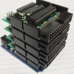
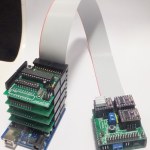
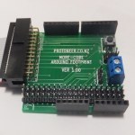
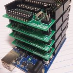
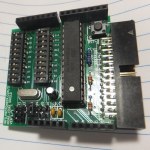
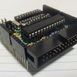
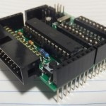
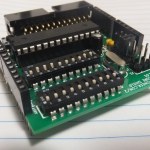
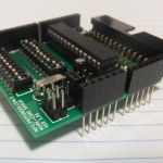
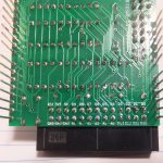
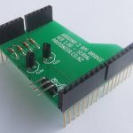
Having the need to do Arduino Hardware testing I decided to make a shield with a secondary ATMega328 micro-controller and ended up with this shield… Behold, an extendable multi-core Arduino!!!
So what can you do with it?
- Well you can start off by using the master Arduino to program the shield. This is done by uploading the ArduinoISP sketch to the master Arduino board and flipping on a few of the DIP-switches.
- I2C – works by switching on the A4 and A5 pins. Basically by doing that you can connect a bunch of these shields together and make them work together. I think this will be pretty useful when we enable I2C on GRBL and start adding devices via g-Code. This will allow you to control spindle speeds or what ever you want or can do with an Arduino.
- The DIL Header(26-pin connector on the side) exposes all the I/O pins of the MORE-CORE shield. I picked the 26 connector so that it’s compatible with the Raspberry Pi cables used with Adafruit Cobbler‘s. On the home front I have designed a PCB that is similar to the cobbler but with an Arduino foot print, enabling you to connect more Arduino stacks from each MORE-CORE shield.
- Serial Communication – My goal with this is to send serial commands to the master Arduino from the shield. This will be very useful for making a CNC control box that takes inputs from switches and rotary dials and turn the signals into commands that can be sent to GRBL via serial comms.
Availability
If you are interested in updates on this project please add your email address to the following mailing list and we will send you more details as they become available.
Arduino More-Core Shield – Mailing List
How to use it.
- Programming the More-Core shield
- Upload the ArduinoISP sketch to the Arduino Board you are going to use to program the More-Core Shield.(ArduinoISP is one of the Example Sketches)
- Set Tools -> Progrogrammer -> ArduinoISP
- Open the Sketch you want to upload to the More-Core shield
- Make sure that you have selected a board type that is ATMega328P compatable. (Arduino UNO or Duemilanove)
- Enable Dip Switch Pin D11 , D12 , D13 on the More-Core shield.
- Insert a jumper on J4. (This enables the ArduinoISP sketch to Automatically restart the More-Core micro controller)
- Using I2C
- Enable Dip Switch Pin A4 and A5.
- Insert jumper on J5 and J6. If multipal shields are being used this only needs to be done once to all pull-up resistors to the I2C bus.
- Hardware Testing
- This shield was designed for hardware testing. The design is very versatile and there are many ways to use it. In my case I wanted to count the number of pulse coming from a certain pin on my Arduino Board. Start by uploading code to the Arduino More-Core board that will set the pin you are targeting to an input pin and then add a counter that will increment when there is a state change. Last bit is to enable the Dip switch that connects to the pin you want to test.
- Jumper functions
- J1-J2 – Used for setting up Serial communication between the Main Arduino and More Core shield
- J1 – Connects the D0(Digital Pin Zero) Pin from the Arduino(AR) to the D0/D1 Pin on the MORE-CORE(MC) shield.(Left AR D0 to MC D1 , Right AR D0 to MC D0 )
- J2 – Connects the D1 Pin from the Arduino to the D0/D1 Pin on the MORE-CORE shield.(Left AR D1 to MC D0 , Right AR D1 to MC D1 )
- J3 – Connects the Arduino’s Reset ping to the 10uF capacitor to prevent auto reset on Arduino Uno’s.
- J4 – Connects the MORE-CORE reset pin to AR Pin D10. This is used with ArduinoISP to restart the Arduino More Core Shield.
- J5 – Connects the MORE-CORE A4 pin to Pull-Up resistor R2. This is used for I2C transmission and only needs to be enabled on one of the I2C units on the I2C bus.
- J6 – Connects the MORE-CORE A5 pin to Pull-Up resistor R3. This is used for I2C transmission and only needs to be enabled on one of the I2C units on the I2C bus.
- J1-J2 – Used for setting up Serial communication between the Main Arduino and More Core shield
Bill Of Materials
- ATMEGA328P – ATMEGA328P-PU-ND
- 28Pin MCU Socket – A100210-ND
- Two 10 switch DIP Switches – CT21010MS-ND
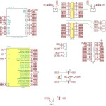
- R1 – 10K (Pull-Up on the More-Core reset pin)
- R2 – 4.7K (Pull-Up for the I2C line)
- R3 – 4.7K (Pull-Up for the I2C line)
- 10uF capacitor – P5134-ND
- 16MHz Crystal – 300-8499-ND
- Two 22pF capacitors – 399-4162-ND
- Right Angled – 26Pin connector – 302-R261/ED10538-ND
- Headers – Female
- Header – Male
- Jumpers
- 6mm Tactile Switch
Gerber Files
Arduino More-Core – Latest GERBER Files
Versions
Version 2.00 (Work In Progress)
- Used SMD ATMega328P (TQFP32 – can use 8, 16, 32KB MCU’s) including resistors and crystal capacitors.
- Kept the through hole crystal because the SMD crystals are very hard to solder at this stage.
- Add two more jumpers(J7 and J8) that enables the Master Arduino(MA) D2&D3 to More Core(MC) D0&D1. This is useful for when you want to make a Serial/TTL proxy that gets commands on the MA Serial pins and forwards it via Software Serial to MC serial pins. With this proxy you can also filter Serial commands and direct them to the I2C bus.
- Replaced the Dip Switches with Jumper because the Dip Switches cost was to high.
Version 1.01
- Initial version.
License and Warnings
This is a work in progress design. All liabilities are on the users at their own risk and they take full responsibility for any harm that might happen to them or their property.

CNC Shield by Protoneer.com is licensed under a Creative Commons Attribution-ShareAlike 3.0 Unported License.
Based on a work at info.protoneer.com/1





Now, THAT is a cool idea! Is there an OS (or proto-OS or whatever the proper name would be) that lets a program use multiple cores? Or is this one program per core kind of deal (still pretty cool tho)?
Thanks for the complements. At the moment its all manual but I can see that applying a protocol like Modbus would work well with this setup. don’t quote me,but from what I understand Modbus will give you the ability to control things down to each pin.
question: are they available, and if so what is the cost.
redesigning this would probably make a decent kickstarter.
I have only made about 5 of them. What do you have in mind with regards to redesign?
Have been thinking of doing a Kickstarter but not being from the US puts on the reserve bench…
Pingback: Hackaday Links: August 18, 2013 - RaspberryPiBoards
Pingback: Hackaday Links: August 18, 2013 — Blog of MPRosa
Pingback: Hackaday Links: August 18, 2013 | OPPATEC
Pingback: Shields | Pearltrees