In the first part of this project I described the technical details of the shield
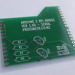
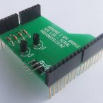
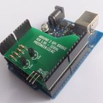
After a few weeks of waiting, I have finally receive the first batch of PCB’s I designed and they look fantastic.
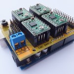
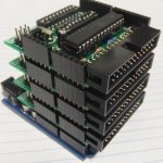
Here are a few photo’s:
- Arduino 2 Raspberry Pi Bridge Shield
- Arduino 2 Raspberry Pi Bridge Shield
- Arduino 2 Raspberry Pi Bridge Shield
So what are the advantages/benefits/pro’s of this little shield?
- Firstly this shield will protect your Raspberry from getting damaged by the high voltages the Arduino’s are running. It also adds a layer of protection where the Arduino might get damaged by external input.
- I picked UART / serial communication because it’s simple to set up. No extra drivers or libraries.
- It uses the standard Arduino footprint allowing you to re-use your old Arduino’s.(Arduino Mega’s are also supported)
- It’s easy to assemble with only 12 parts. All parts have through hole footprints making it easy to solder.
- Using the Arduino’s on-board 3.3 voltage regulator, it reduces the number of bridging wires. (3 in total).
- Right Angled headers ensures that the connection wires exits at the back of the shield.
Preparing the environment
Lets start with the Arduino. Upload the following serial echo sketch to your Arduino.
|
1 2 3 4 5 6 7 8 9 10 11 12 13 14 15 16 17 18 19 20 |
int incomingByte = 0; // for incoming serial data void setup() { Serial.begin(9600); } void loop() { // send data only when you receive data: if (Serial.available() > 0) { // read the incoming byte: incomingByte = Serial.read(); // say what you got: Serial.print("Input:"); Serial.println((char)incomingByte); } } |
By default the Raspberry Pi is set up to write debug/status messages to the on-board serial port.
To disable this we need to make some changes. Run the following command to start…
|
1 2 3 |
sudo nano /etc/inittab |
Change: T0:23:respawn:/sbin/getty -L ttyAMA0 115200 vt100
To: #T0:23:respawn:/sbin/getty -L ttyAMA0 115200 vt100
|
1 2 3 |
sudo nano /boot/cmdline.txt |
Change: dwc_otg.lpm_enable=0 console=ttyAMA0,115200 kgdboc=ttyAMA0,115200 console=tty1 root=/dev/mmcblk0p2 rootfstype=ext4 elevator=deadline rootwait
Removing all references to ttyAMA0 (which is the name of the serial port).
To: dwc_otg.lpm_enable=0 console=tty1 root=/dev/mmcblk0p2 rootfstype=ext4 elevator=deadline rootwait
Restart the Raspberry Pi to apply the changes.
|
1 2 3 |
sudo reboot |
Testing
To test if it’s working you can start-up Putty or if you want test it in the shell by installing minicom.
|
1 2 3 |
sudo apt-get install minicom |
Connecting:
|
1 2 3 |
minicom -b 9600 -o -D /dev/ttyAMA0 |
If all went well it should echo back all the characters you entered.
Next step for me is to write a little application that talks to my CNC software (GRBL) via this shield.
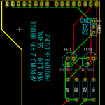
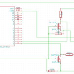
Below is the Schematics and board layout.
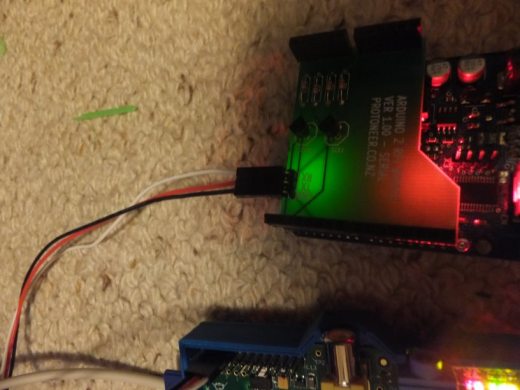
Just a small update on how I wired the cables up…
- rPi Bridge Shield Gnd Pin -> Raspberry Pi Gnd
- rPi Bridge Shield TX Pin -> Raspberry Pi Pin 14 (Red Cable)
- rPi Bridge Shield RX Pin -> Raspberry Pi Pin 15 (White Cable)
For more help on locating the correct Raspberry Pi Pin have a look at the Raspberry Pi Pin-layout page.
To round it off, I have some spare PCB’s if anyone is interested in trying it out.




Really love the idea that Arduino is now married to Raspberry Pi. You are really inspiring. Would you mind sharing the board layout with me?
Hi Chris,
Thanks for the kind words. I have attached the schematics and board layout. I also have the KiCad files if you are interested.
Kind regards,
Bert