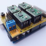
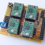
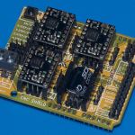
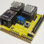
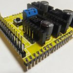
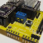
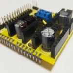
Do it yourself CNC projects are popping up everywhere and we decided that we wanted to contribute to the growth.
Here are a few of our design goals:
- Modular Design – We wanted to do more than just keep cost down. We wanted things to be reusable and up-gradable. (Arduino , Individual Stepper Motor Drivers and more…)
- Compact Design – Squeezing a 4 axis design into a board the same size and Arduino Uno.
- Opensource Software – 100% GRBL compatible (G-Code Interpreter)
- Opensource Hardware – Arduino has opened up the power of micro-controllers to everyone. (Easy but powerful computing)
- Evolving Development – We are keen to improve on the design and welcome all feedback.
NOW AVAILABLE at our Ebay store… http://stores.ebay.com/Protoneer
… or in assembled from from Elecrow.com
Arduino CNC Shield V3.10 – GRBL v0.9 compatible (PWM Spindle + Soft limits)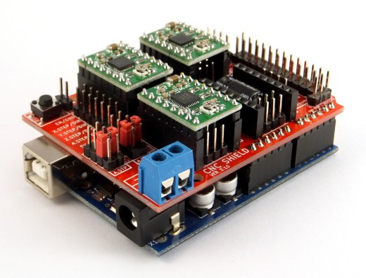
Arduino CNC Shield V3.00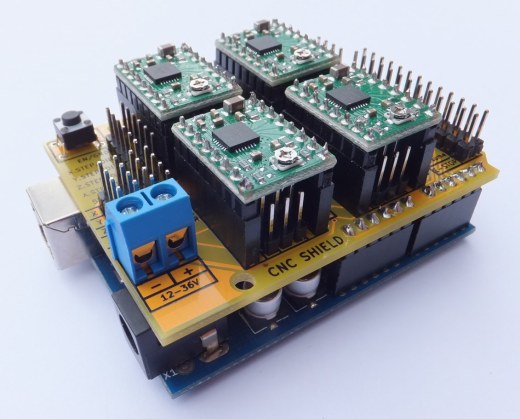
Arduino CNC Shield V2.00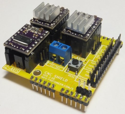
- Availability
- Board Layout
- Bill Of Materials
- Assembly
- GRBL Software/Firmware
- Versions
- Gerber Files
- License and Warnings
- Extra Reading
Availability
NOW AVAILABLE at our Ebay store… http://stores.ebay.com/Protoneer
… or in assembled form from Elecrow.com
If you are interested in updates please add your email address to the following mailing list and we will send you more details as the shield develops.
Arduino CNC Shield – Mailing List
Board Layout
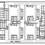
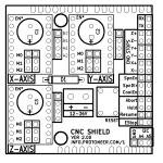
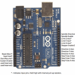
The following image displays the functionality of the Arduino pins as used by GRBL.
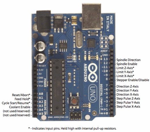
GRBL Pin Layout
We have designed the Arduino CNC Shield to use all the pins that GRBL implemented. We have also added a few extra pins to make things a little easier.
Extra pins:
- Limit switch pins have been doubled up so that each axis has a “Top/+” and “Bottom/-“. This makes it easier to install two limit switches for each axis. (For use with a normally open switch)
- EStop – These pins can be connected to an emergency stop switch. This does the same as the RESET button on the Arduino board. (We do advice that an extra emergency button also be installed that cuts power to all machinery. A REAL EMERGENCY BUTTON)
- Spindle and coolant control has their own pins.
- External GRBL Command Pins have been broken out allowing you to add buttons for Pause/Hold , Resume and Abort.
- Serial Pins (D0-1) and I2C Pins (A4-5) have their own break out pins for future extensions. I2C can later be implemented by software to control things like spindle speed or heat control.
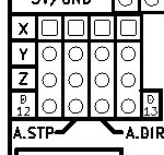
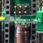
- Version 3.00 of the board added a jumpers to configure the 4th axis(Clone the other axis’s or run from Pin D12-13), Comms Header(RX+TX , I2C) and a Stepper Control Header(All Pins needed to run 4 steppers)
Bill Of Materials
- Arduino CNC Shield PCB
- 100uF 50v 8mm High Capacitors (493-3289-ND)
- Jumpers (A26228-ND)
- 8-Pin Female Headers(S7006-ND)
- Male Headers(A26514-40-ND)
- Tactile Switch (450-1650-ND)
- Screw Terminal 5mm (A97996-ND)
- Pololu Stepper Drivers . (Please note that the shield was designed to work with A4988 compatable polulu drivers)
- 10K pull-up resistors
Assembly Instructions
Click here for the Assembly instructions for the Arduino CNC Shield V3.XX
Click here for the Assembly instructions for the Arduino CNC Shield V2.XX
GRBL Software/Firmware
GRBL is opensource software that runs on an Arduino Uno that takes G-Code commands via Serial and turns the commands into motor signals.
The GRBL source Code is located here.
I have also written a few turorials on uploading the firmware onto an Arduino Board:
- Quick GRBL setup guide for Windows
- GRBL Arduino Library – Use the Arduino IDE to flash GRBL directly to your Arduino
Versions
- Version 3.10
- Added Support for GRBL 0.9v with PWM Spindle.
- Version 3.00 (4 Axis)
- Enlarged board to add a 4th Axis that can clone the X,Y or Z axis. With a 4th option to use pin D12-13 to control it.(Setting up the 4th Axis)
- Added a breakout header for all the Axis’s.
- Added a communication header for UART(Serail) and I2C.
- Added the a connector for an optional fuse.(Fuse not supplies as it needs to be selected for the current that will be used.)
- Capacitors are mounted horizontally giving more clearance between them and the stepper drivers. Good for ventilation.
- Added a pull-up resistor on the axis enable pins. This prevents the pin from being in a floating state.
- Added 2 mounting holes
- Version 2.02 (3 Axis)
- Fixed High Voltage label
- Removed Diode D1.
- Reduced the number of Via’s.
- Version 2.01
- Added a 5V Breakout
- Filled in both sides with Ground Copper
- Moved RX/TX pins to the side so that 26-Pin header can be used. Same as the headers on a Raspberry Pi.
- Small Text Changes
- Version 2.00
- First official version of the CNC Shield.
- All pins used by GRBL has been broken out.
Gerber Files
Arduino CNC Shield Ver3.00 – Gerber Files
Arduino CNC Shield Ver2.xx – Gerber Files
License and Warnings
This is a work in progress design. All liabilities are on the users at their own risk and they take full responsibility for any harm that might happen to them or their property.

CNC Shield by Protoneer.com is licensed under a Creative Commons Attribution-ShareAlike 3.0 Unported License.
Based on a work at info.protoneer.com/1
Extra Reading
- Build Your Own CNC Machine – By James Floyd Kelly and P. Hood-Daniel
- CNC Machining Handbook: Building, Programming, and Implementation– By Alan Overby
- Pololu Stepper Motor Drivers – http://www.pololu.com/catalog/category/120
- Pololu FQA covering how to connect stepper motors – http://www.pololu.com/catalog/product/1182/faqs
- GRBL Wiki including upload, setup and running – https://github.com/grbl/grbl/wiki/_pages
- GRBL Supported G-Codes – www.shapeoko.com/wiki/index.php/Grbl
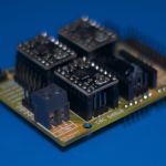
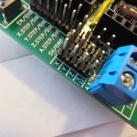
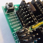
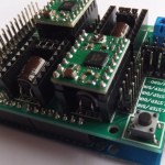
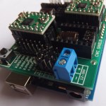
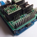
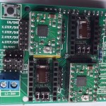
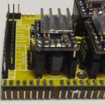
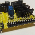
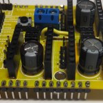
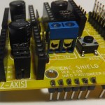
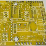
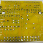



Nice looking shield. Any links to retailers, or better yet the board design?
I can’t find it in your online store.
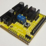
Thanks for the complements. We are in the process of beta testing the shield so that we can finalize the design.
Would you be interested in being a Beta Tester?
Bert,
Definitely, I have actually designed a board and made my own prototype shield, but yours is more compact and better laid out.
Will even pay for it if necessary. Send a private e-mail if interested.
TomJ
Thanks Tom… I will send you an Email shortly.
If anyone else is interested please let me know, so that I can finalize the design and get it out there.
I’m interested in beta testing. I’ve got 3 pololu drivers and stepper motors just waiting to be used.
Hi David, I have sent you and email.
I’d like to beta test as well if at all possible. I have a project that needs a control board. I have the drivers, motors, and arduino.
Thanks.. I have sent you an email with the details.
Hi Bert!
I have finished bild my cnc project and looking for control board. I plan to use Arduino Uno controller. You board is nice I could try to use device as a Beta tester .
I can do… Will send you an email shortly. 😉
I also would like to be your beta tester. I am also prepared to pay for this.
Will send you a mail shortly… 😉
Hi, im VERY keen on your CNC board, Im going to turn my old mill into a CNC and also thinking about building my own CNC foam cutter for work. im happy to pay for this board, also happy to beta test. cheers Ben
Hi Ben, thanks for the interest. I will send you email with details shortly.
VERY keen to get my hands on this, i have a few CNC projects i want to build and this looks like it will be perfect. please email me about purchasing and beta testing.
thanks
haha… That’s exactly why I designed this little shield. I wanted a CNC board that’s modular and as reusable as possible.
Also have a few more ideas for extensions but I will work on that after I have received so feedback from users.
Pingback: GRBL compatible Arduino CNC shield - RaspberryPiBoards
Pingback: GRBL compatible Arduino CNC shield | Blog of MPRosa
Pingback: How to create an Open Source CNC | Alan C. Assis
Hi, I am building 2 CNC’s. One for milling and one for Laser cutting, etching. I am using 5Volt Nema 17’s.
This would be perfect if it could use the DRV8834 module.
Can I be a beta tester or can you sell me a bare board or the files to have it made?
Thanks Robert… I have sent you an email with the details. At the moment there are a lot of people asking to be beta testers so I can only do one kit at the moment.
I have also uploaded the Gerber files if you would rather get the boards made…. Kind regards,Bertus.
mail me the details on testing.
Willing to give it a try. 😉
Details have been emailed.. 😉
Nice looking shield. I am a long time user of GRBL and one thing that comes in handy on a GRBL shield is a socket for an optional 4rth stepper driver that can be used for a second motor on the Y-axis. Jumpers that can slave this 4th driver to the standard Y-axis stepper signal, and ideally, an optional logic inverter on the direction pin for the 4th driver.
Yes… I was looking at that option, but I was running out of room on the shield.
A nice option would be to have a jumper configuration of some kind that allows you to select what axis you want to double up.
How exactly does “doubling up” work? Does that mean that whatever steps are sent to the one driver are sent to the other, or what? If you wanted to have a fourth axis separate, like for an Extruder or something, you could have take the spindle enable pin, and the spindle direction pin, and make those direction and step.
How hard would this be to do in GRBL? I know it would be doable outside of GRBL in your own sketch.
(Also, I want to beta test, but the other post hasn’t showed up yet, and I don’t know why)
Thanks for the question. I have added a little section on Beta testing.
By doubling up you are basically just connecting 2+ stepper drivers up to the same stepper and direction pins.
Using those pins would be an option. But the way GRBL was designed will not make it easy. GRBL is very efficient at what it does and
sends pin changes in one call. So stepping pins need to be on the same I/O port as I understand it. (The Spindle pins are not on the same port as the stepper pins)
I however still think we need to work on adding I2C support to GRBL so that you can extend it with custom hardware till kingdom come.
I though about it a bit more. You might be able to get away with the current GRBL code as it is.
By using the Spindle enable, direction and the coolant control pins for signals I can create a shield that activates an extra extruder stepper driver with the spindle enable pin. Set the direction of the extruder with the spindle direction pin and turns the extruder heater on and off via the coolant pin. You could also interact with the pause pins on GRBL to make the setup wait for the heater to reach the right temp before starting.
It will take a bit of effort but its more than doable.
The best solution though would be if we could enable I2C in GRBL. But that will take a lot of effort.
Does feed/hold require an M1(Optional Stop) command in the Gcode? Or is this a hardware function?
This is a hardware function and from looking at the code it looks like an interrupt is linked to the pin stopping the movement queue.
I see, gotta be careful with that then. Some operations are not meant to be stopped in the middle, with feed off and spindle (or whatever is controlled as a spindle) still running. If this is a real emergency, then I suspect the RESET is the right button for that. But if it’s a convenience thing, I would much rather see it stop at a preset point in the program.
Do you know by chance if Grbl recognizes M-codes, and specifically M1?
Thanks!
Mmmmm it supports the following g-codes . From the looks of it it,it does not have M1… But it does have M0 that’s a program pause. What you also need to consider with GRBl is that it does not just take a g-code file and run it. You need to constantly feed it with new g-code commands.
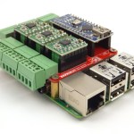
For that reason I designed a Raspberry Pi to Arduino Bridge shield. http://blog.protoneer.co.nz/arduino-to-raspberry-pi-bridge-shield-pcbs-finally-arrived/
The Raspberry Pi is excellent for streaming g-code commands to GRBL and with a bit of effort you can create a nice Web-interface for the rPi that you can upload g-code files to and it will send it off to your CNC machine.
I do the same thing with my 3d printer, except I don’t use a shield, I just send it over USB. I use a BotQueue.com to control the 3d printer. I just send it a stl file, and it slices it and sends it to the printer. You can also send raw gcode if you want to. I’d like to get one of those shields you are talking about and make sure BotQueue can work with it.
I’m assuming these are the boards you’re talking about: http://blog.protoneer.co.nz/arduino-to-raspberry-pi-bridge-shield-pcbs-finally-arrived/
Yes, that’s the one. It should work because instead of pointing the to the USB serial port you just point to the rPi’s hardware serial port. Will send you an email in the next day or so about beta testing. Just remind me about the rPi Bridge if I forget about it.
Pingback: » Shield CNC para Arduino - hacedores.com
I have spare A4988 stepper motor driver carriers used on 3d printer Reprap RAMPS, will these work on the shield?
I’m looking to use this board on a Sumpod 3d printer and a small hobby lathe I just got.
Thanks Mark, I have sent you an email. Like your website by the way.
(I have always wondered if it was possible to hack cheap digital scales like you have done on your site. )
If you have any more of these for BETA test I’d love to be involved.
Thanks Richard… An email is on its way.. 😉
Add me to the list of beta testers please, already have the pololus that I never wound up using for the printer parts plotter/laser cutter because I got frustrated.
Email is on its way… Hopefully this will not be to frustrating. I a working on the assembly instructions that would also help alot. 😉
Looking really nice. What sort of speeds can you get running a 3 axis machine?
Hard to tell… Should be in the same ranges as the speeds you can see on the Delta 3d Printers.
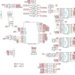
Your shield looks really good. Can you post the schematics? I would love to take a closer look at your design.
Thanks for the request Jan. I have uploaded it for you… Please let me know if you have any suggestions on how I can improve the circuit.
Pingback: Znowu o CNC czyli DIY Arduino CNC - techfreak.pl
Great sheild..
Do you have the 2.01 Gerber Files as I would like to make some PCB for testing on my drill mill.
Hi Auzze… I have uploaded Version 2.01. Please let me know how your project goes. 😉
I’m interested in beta testing, if there’s still “space.”
Thanks Matthew, I have emailed you the details.
Hi Id love to get this off you prepared to pay for it as well
Thanks… I have send you an email with the details. 😉
Pingback: Microcontrollers & Boards | Pearltrees
I am highly interested in buying the product or/and testing it out.
Thanks for the interest… I am currently waiting on parts. Will let you know as soon as they are available again.
Very interested in this shield for testing. Our cnc is finished, just choosing electronics. Please give me more info on getting one of these.
Thank you
Hi Dustin.
We are currently waiting on a few of the components for the boards. I will be in contact as soon as its available again.
Is there a sign up for e-mail notification for finished boards?
Thanks for the question Shane. I have setup a mailing list for people that wants to get a notified when the shields are ready to go. Arduino CNC Shield – Mailing List
Hi!
I want to build my own cnc machine with arduino, and this is a very interesting board. I want to make a PCB for me, so can I get the more details in e-mail?
Hi Daniel,
I have sent you a quick email. Most of the stuff has been covered with this webpage. The GERBER files is the important stuff you need to get the boards made.
Bert,
Any chance you have looked at this shield from Reactive Substance:
http://www.reactivesubstance.com/step.html
I just got it but am looking for more. I like your shield, but wish it had a second y-axis. Perhaps there is something to be learned from his design.
Thanks for your comments…. The Buildlog.net Stepper Shield was one of my first inspirations.
Interesting… Can you provide a bit more details on your setup. I have seen lots of machine with double-stepper Z axis.
I have also seen that you can run 2 stepper motors from one Pololu Driver. Could that solve your issue or do you need to run two separate Pololu stepper drivers on the Y axis?
excuse me, i can’t open the file, can you post the download’s link of the program?
I usually use some of the free online viewers like
HI..
Can you please explain the microstepping pins.
Auzze
Hi there….
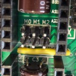
Its pretty easy. It depends on the driver you use. A4988 – http://www.pololu.com/catalog/product/1182 if you scroll halfway down the page to “Step (and microstep) size” you will see a table with M1,M2,M3. The table explains how to set the micro stepping.
For Example having all three jumpers inserted will give you the smallest micro-stepping your driver can do. Removing all the jumpers will remove micro-stepping and the driver will run on full steps.
The DRV8825 works on the same system but has a bigger range of micro-stepping.
Does that make sense?
Hi Bertus
Really like this board and I have downloaded the gerber files.
Being new to milling pcb boards i have no idea what software works best to take your files and generate g code for milling. Not even sure what program you used to create the files themselves. I downloaded eagle and seems it cant open the drl file.
Is there a better software you use to drill and cut the pcb? or am i stuck making a cnc board using another process? I would love to cnc mill this board using a grbl cnc.
any help would be greatly appreciated.
Hi Ron,
Thanks for your support. These boards are actually on the complicated side to make on a milling machine. That is because they are two sided and it has via’s that goes from the top to the bottom layer. You might be better of getting a few of the boards made a places like http://www.elecrow.com/services-c-73/pcb-fabricate-service-c-73_116/ or http://imall.iteadstudio.com/open-pcb/pcb-prototyping.html.
This little hand website can convert Excellon Drill files into G-Code -> http://eng-serve.com/cnc/excellon_gcode.html
Copper CAM is also a very handy app to mill Gerber files with. http://www.celeritous.com/estore/CopperCAM
Hope this helps. 😉
johan..
i want to know where i can buy this arduino shield for the cnc
and what are the cost for shipping to the netherlands
I hope for an answer
Hi Johan,
Thanks for your interest. I have not yet said it out to loud, but I have listed a few of my latest boards on Ebay. http://www.ebay.com/itm/Arduino-CNC-Shield-GRBL-compatible-Uses-Pololu-Drivers-/281172504775?
Enjoy. 😉
Dang missed out!
Will you be doing another run of these? Really keen to get my hands on one, or two
Hi Morgan,
The new Version 3 boards are on their way and should be back in stock by the end of the week. If you want to get notified when they arrive I would suggest that you subscribe to my notifications mailing list : http://eepurl.com/DIq-z
Are you from NZ by any chance? If so you might want to have a look on Trademe… 😉
Is the v3 board available for sale yet? Can I buy the PCB only (no components)
Hi there,
I have added a buy-now button to the following page(http://blog.protoneer.co.nz/arduino-cnc-grbl-shields-boards/) if you are interested in buying a kit. I was thinking of selling only the PCB’s but it works out cheaper buy the kit with all the parts included ($25 including world wide shipping).
Please send me your bank details so that we can make an international transfer in order to purchase Arduino CNC Shield – 100% GRBL Compatable.
we are located in Bangalore, India.
with regards,
Elechem Technik Pvt Ltd.,
Bangalore, India.
Hi.
I have added a Paypal Buy-now button on the following page http://blog.protoneer.co.nz/arduino-cnc-grbl-shields-boards
I am working on getting more listing on eBay, but because I am a new seller on eBay I am only allowed to sell a few items per month.
Regards,
Bertus.
Pingback: Protoneer CNC Shield | CADduino
I just got mine soldered and it’s working perfectly! Goodbye messy wires!
Thanks for the update. I you have a few photo’s pf you systems that would be much appreciated. 😉
Hi Bert,
I have a question about the GRBL controller.
What for a GRBL controller to use you?
Your new shield (v3.0) has the option for X/Y/Z end stop and spindle DIR/EN, but I have no idea what for a software work and supported these options.
MACH3 use a shield which support the parallel port (no compatible with arduino), and the GRBL controller (v3.5) not supported these options.
Do you have a configured or a special software?
It´s fantastic if you can help!
The shield I have buy over eBay and if it´s received I will use this with my cnc mill.
Thank you in advanced!
Regards,
Sven
Hi.
I use a software called universal Gcode sender to send commands to my GRBL board. http://www.shapeoko.com/wiki/index.php/Universal-G-Code-Sender
GRBL is the firmware that runs on the Arduino board and you can send it special G-Code commands that enable the spindle pins. The end stops are
little switches that you connect to the pins on the board and they will stop the machine if it reaches its maximum capabilities.
Hope this helps.
Regards,
Bertus
Hi,
I am just checking out the GRBL shield V3.
I use the board together with 3 polulu DRV8825 stepper drivers.
On the polulu website I found out that in order to use the driver, the reset and sleep input should be put high. Based on the GRBL shield schematic I think the normal operations is low for reset and sleep. Does anyone know if I can configure something or set a jumper in order to get them high?
Thanks in advance,
Rene
Hi.
The DRV8825 driver works with the V3 board and does not need any modification. Just make sure you use the second version of the DRV8825 as the first one needs an extra resistor to be compatable with the A4988 footprint.
hi witch one one of the drv8825 is the sec version i have one with md20b is this the newer version
and if this is not how can change to let it work
ps is there of de version 3 a schematiclayout i see onely version 2 schematic layout on your site
Yes.. the MD20B is the good one. The A version needs a 10K resister to make it work…
Pingback: BLOG | New Product Post – 3D Printer Accessories
Hello, can I use the Pololu A4988 and 5V Stepper Motors like this
“http://www.ebay.de/itm/Auto-Stepper-Schrittmotor-DC-5V-1-2A-1-8-Degree-CNC-Nema17-2-Phasen-4-Draht-/321284446618?pt=Motoren_Getriebe&clk_rvr_id=574829651624”
with it ?
Yes you can… 😉
Hi , recently I’ve bought one of your amazing shield to use it with DRV8825 polol driver . and when testing the steppers with shield by making them rotate only once , the motor rotate for half a rotation then vibrate then continues to rotate .
Can you please suggest a solution for this issue .
Hi…
There could be a few issues. You will have to play with the max speed and acceleration or steps per mm in GRBL. It could also be that you are not giving it enough current. Using full stepping can also cause this issue(Try 1/2 step or less if thats the case).
Regards
I had a similar symptom when using the same setup and Nema17 4800g/cm steppers. The problem went away with a very slight load on the stepper shaft. I’m picking that, under no load, the current draw is at it’s minimum, and that’s not quite enough to bring the stepper into the next step (that bump you feel when rotating the shaft by hand) It then appears to sit there and bounce between 2 steps, giving off a really disconcerting buzz/vibration. By applying a small load, the current draw is increased, and the motor starts to behave.
I have set this up to slave the A to the Y axis and am getting movement on A but not on Y. If I remove the A driver and send commands to the Y/A I just get a hiss but no movement. I’ve shifted the Pololu DRV8825 from the A to the Y and no change.
Any suggestions?
Hi. The A axis can only clone other axes or run of the D12 and D13 pins. Hissing is a good sign cause that means the drivers have been enabled but is waiting for stepper signals. Are you using GRBL or writing custom code by the way?
Hello,
I have the 3.0 version.
The stepper on the x axis moves much slover as the one that is on the y or z axis.
If i connect the stepper from the x to the y or z axis with the same driver it turns normal.
If i clone tbe x axis to the A axis it is the same Problem.
Hope you understand what i mean
Do you have any solutions for the problem?
Best regards.
Hi There. This will be to do with your GRBL settings. Make sure the X-Axis set to the same mm/min and it should be good.
Hi,
This is it!
I found it out yestetday evenig.
Must be a long time ago, where i hab changed it *confused*
But now it works pretty well.
Thank you for your help 😉
Hello there
I have just started playing with the CNC shield version 3.03.
I’m currently struggling with the end stops:
Until now I only managed to stop the axis when one of the end stop switches is reached. Then I have to reset the board which is fine. After that the axis will move to both directions. I think that’s a bit odd.
Wouldn’t i be more convinient / safe in this cenario if the axis would only be able to travel away from the reached end stop?
For example:
– The X-axis travels positive and reaches the positive end switch
– The X-axis is being stopped
– I press reset
– The X-axis is enabled to travel to the negative direction only as long as the positive end stop is still active.
Is this possible with the current shield? Am I missing something?
Kind Regards
Marcel
Hi Marcel,
Best would be to ask the above questions on the GRBL page as they will be able to advise what the best way would be to achieve this.
https://github.com/grbl/grbl/issues?state=closed
Regards.
This is a very good board. I am using it very successfully for about 3 months with my Shapeoko 2. 4-Stepsticks and Nema17 70oz/in motors @ 12V (pc power supply) driving a dremel tool as the spindle.
I plan to upgrade to 8825’s to drive Nema 23 140oz/in motors @ 24V shortly to support a much bigger Dewalt 611 router. It is nice to be able to use the same board/firmware. I have used GRBL 0.8c and 0.9b successfully. The shipment got to me in the US without any problem or delay.
The assembly was very easy and followed the supplied directions perfectly.
My Shapeoko build log is here: http://www.shapeoko.com/forum/viewtopic.php?f=5&t=2381
Thanks for your support of my little CNC board. Your projects looks great!!! Keep up the good work… 😉
Hi, i bought the 3.03 on ebay, it works great, but endstops doesn’t works.
I try with normaly open contacts, like this ( X+ ._. dots are connectors and _ a wire, so normally the motor X+ stop but not mine)
Do you have a schematic or a picture to wire it ?
Hi.
Schematics is available here : http://blog.protoneer.co.nz/arduino-cnc-shield/arduino-cnc-shield-scematics-v3-xx/
Endstop configuration : http://blog.protoneer.co.nz/arduino-cnc-shield-v3-00-assembly-guide/#EndStops
Did you add the needed jumper as per the above link?
Hi,
i try with normaly open switch, with three configuration of the bottom right jumper, i test in VCC and in GND (high and low) and without jumper but doesnt works.
So normaly if I put a jumper for example on X+ when the motor turn in X+ it will stop it, but not mine.
Thanks for your help
Hi.
Do you have endstops enabled? I think its setting $16=0 (hard limits, bool) from memory. https://github.com/grbl/grbl/wiki/Configuring-Grbl-v0.8
Regards.
Pingback: Cheap Chinese Laser Cutters – Buying one | Protoneer.co.nz
Pingback: Sneak preview : LPCDuino | Protoneer.co.nz
Pingback: Protoneer CNC Shield + Alamode + Raspberry Pi CNC Controller | Protoneer.co.nz
Hi what motors can i use on this board please?
Hi. The limit sits with the Stepper drivers that you use… The A4988 and DRV8825 Max out at 2Amps. So they will only work efficiently with motors in that range say a Nema17/23. For bigger motors you can still use the board will have to use the headers on the left side that breaks out the stepping and direction pins for each axis.
I’m a cnc machinest and I recently stumbled on the ardunio and related info. I am very interested but want to finish the research before I jump in. Looking at the Nema 23 from Phidgets # 3307. But how do you supply power to 4 stepper controls? Do you use a 24 volt w/ 6 amp power supply with 4 taps of only about 1.5 amps out for each or do you use a 6 amp and connect each shield in parallel? and hope that everything equals out!
Thanks for the help. I’ve been hoping something like this ardunio and GRBL etc would come along for a long time. I want to play at home on my stuff.
Measure twice cut once… 😉 To driver 3x 2A motors I suggest you get at least a 6-8Amp power supply. Need to add the max current per stepper driver times n-number of drivers. Extra amps will ensure the Power supply does not get stressed to much. The shield has a single power input for the stepping driver side of it and the logic bit gets powered by the Arduino. 2A Nema 23 is about max that the Pololu Driver can run. For more you will have to look at external Stepper drivers like Gecko’s… But that gets very expensive and multiple power supplies might be needed.
I bought this board and want to clone the 4th axis to the Y axis. How is this done?
Hi. Have a look at the following link . It explains how to copy any of the axes.
Pingback: Arduino shield for CNC-machine with GRBL | Swedish Prototype
I need to be able to enable X and disable A and/or enable A and disable X. I am making a 4 axis table top router and will be “faking” rotery (A). The A drive will be a built in drive running at the same time that X is. I need to disable X so the table doesn’t move and hit the limit switches. If I apply 5 volts to any EN pin, will that disable all four drivers? Thanks, Carl
Hi Carl,
One of the artifact with GRBL is that because there are a lack of pins on the Arduino Uno one pin enables/disables all of the stepper drivers. So yes, driving the EN high will disable all. You can however cut the enable track on the A-Axis and control that individually.(A 10K pull-up resistor would be good to keep it stable and and extra control pin will be needed to drive it.)
Thanks for your answer. I was also thinking that if I cut off the EN pin from the driver board and solder it sticking up I could use it like a male plug and wire that to an EN switch. I hate to cut your board. Thanks, Carl
I have the enable pins working fine now. I pulled the en. pins from the driver boards and put them on top as a male plugs.
I do have one more question, WHAT DOES G R B L stand for? I can’t find the meaning anyware. Carl
Not sure about the name… But it works very well. 😉
Hi,
I want to know ,Can i use this board to make the hybrid CNC & 3D printer ?
This shield is more targeted at the CNC side and will require some modifications to make it capable of also doing 3d printing work.
Hello. the shield is great! works fine with nema17. But I need to upgrade to nema23. I have a 24v 30A power… with nema 17 works fine, but when i change the stepper…. when I put the nema23 don’t work… I am frustated… any idea???
thanks all.
sorry for my english
Thanks for the question. Are you sure you have connected the cables correct? Are the steppers making any noise? What amps are the steppers rated?
hello! thanks for anwser…. the problem was ldo steper wiring!!! Ldo has 3 different datasheet with different wiring colors!!!! Now move!
Another questions…. with me pololu a4998 I can only use 2A…. Nema23 is 2.8A per phase…. another compatible driver????
Thanks for all
great project!!!!!! works fine!!!
The A4988 will driver the 2.8Amp steppers. The next bigger step is to get external drivers like Gecko drives but they are very dear and might be an over kill. (The breakout pins on the left were designed for external drivers.)
Pingback: Raspberry Pi Alamode CNC Controller -Use Arduino for Projects
Are the holes plated?
Hi Jack,
Yes, the boards I sell are gold plated.
Regards.
Pingback: Axis Motion: Design Choices II | CNC Design Blog
I have a question: Does this shield also support stepper control from the Arduino libary, for example with the stepper libary:
http://arduino.cc/en/Reference/Stepper
I’m organising an University project for 60 groups and this would be an ideal shield!
Titus
Hi Titus,
The shield is a little more complex with it being able to control 3-4 stepper motors. Code wise its not that hard to control and will use similar code to the library you mentioned.(All that the codes does is sent an enable pin, direction pin and then toggles a step pin to create movement.)
Sounds interesting let me know if you need help.
I am not a technical guy. How do I connect this shield to the computer and how do I connect the steppers to the shield.
I would very much appreciate a tutorial with the necessary info to assemble the whole thing.
Thanks.
Hi Ed. I would start by paying around with Arduino’s. Once you understand how they connect to your computer it would make much more sense.(They just plug into your computer like a printer via USB cable). My little shield/board plugs into the Arduino Micro Controller. On top of my shield/board are headers to plug in stepper more to drivers made by a company called Pololu. The Stepper motors them self plug into my shield/board. From there all you have to do is open up a serial terminal app like putty or even better with GRBL you can use Universal G-Code sender that will allow you to easily connect to the CNC board. Hope this helps. There are also plenty of tutorials online, just google GRBL or shapeoko .
i am interested in using this and i am willing to beta test it. my big easy drivers keep burning out and im sick of wasting money so you just might have an answer. at 2 amps this should easily run my steppers. correct me if im wrong but i believe it states that your board runs at a max of 35v? thats plenty for me but i was wondering if it can go higher? (my psu is a 50v 1.5A) if not it is fine. i will just step it down a bit. this is a cnc im using for a school robotics team so a quick reply is requested.
Hi Joshua, the rated voltage on the board is for the supported Pololu A4988 drivers that can take a max voltage of 35v. ITs likely that you are supplying your Easydriver to much voltage as they are rated up to 30v.
Hey!
I’m trying to install a micro servo on a CNC shield V 3.03, But I do have a problem, I don’t know where to put the 3 pin connector on the board? I’ve already watched some youtube vids to get to know some of the basics, however our main problem is where to connect the signal wire. Could you help me out?
Thanks in advance!
GRBL is the software I use with the shield and it works with Stepper motors instead of servo’s. I would suggest this shield if you want to drive servo’s ->
Pingback: [News & CNC] Elle est enfin là (et ça promet du lourd) | Skyduino - Le DIY à la française
Pingback: GRBL compatible Arduino CNC shield | Hackaday
Pingback: GRBL firmware & stepper driver esterni » Indie Gear Lab
Pingback: CNC Projects | Pearltrees
hello, I have this shield with drv8825. the question is: 12v 15AH computer power supply, works well one nema17 if I turn 2 or 3 nema17 they do not work. If i used power supply 24v 15AH 360W, on 3 nema17 they works, but the drivers get very hot and high temperature. how can I have the drv8825 working with 3 nema17?
The drivers are constant current drivers and will get warm. Heat sinks and a fan will increase current they can run at be fore they cut out(They have thermal cut-off). Check the 12V power supply, might be faulty.
Pingback: Stepper does not turn | CL-UAT
Is CNC shield compatible with GBRL firmware 4 axis as below?
https://github.com/LETARTARE/Grbl-xx_with_Arduino/tree/master/Grbl8c2Mega2560
Thanks!
Ciao…
No, I don’t think so.
Hello, I just bought one of these shields and 4 drivers. I’m trying to make them work but I wont use g code. I want to make my own code cause I wont use it for a cnc. I put only one of the drivers and try to simply put the enable pin (pin 8) on LOW, the X direction pin (pin 5) at any stage and give a pulse on X step pin (pin 2) but the motor didn’t do anything. I have the new version of the DRV8834. Could you give me some advice?
Thanks in advance!
Hi Ernesto, what you are doing sounds right. Pin 8 and direction pin low. Then Pulse the stepper pins on and off say every second to start at. Be sure to keep the voltage down as the DRV8834 drivers are low voltage.
I would like to see someone try this shield on a Intel Edison with a Arduino interface. Seems like you could get much better performance.
Yes… that would be interesting.
Hi Bertus,
I am in the same seat as Ernesto. Not for a CNC, using an Arduino Uno and I want to use the 4 DRV8825 drivers independently for a robot. I love the small size of your board.
I have X,Y,Z working correctly but can’t see how to use the A axis other than as a duplicate of the other 3.
Can you please tell us how to adress that A driver ? what pins can be used on the Uno and how ? FWIW, I don’t need the pins for coolant, spindle and limits switches.
Thanks for your help
Answering my own question :
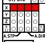
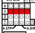
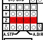
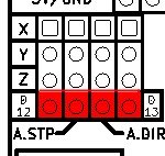
Just install the 2 jumpers labelled D12 and D13 above the Motor power connector. That will connect the Digital pin 12 and Digital pin 13 (normally used for the spindle) to the Step/Dir pins of the A driver. Driving the A motor is then just like the other motors. And now, on to the software … 😎
Hello,
How would I install GRBL 0.9g in place of 08c?
I want to try the newer code and test the claims on Github.
Have you tried it?
Thanks
Answered my own question with a quick google search.
Seems the answer is on the GRBL wiki.
https://github.com/grbl/grbl/wiki/Compiling-Grbl
It’s in and running!
Thanks
James
Great stuff.. 😉
Hi. Are the DRV8825 drivers overheating maybe? I know they are very sensitive to heat and the thermal cut-off works to well some times. Might be worth dailing them back a bit if they are very warm.
Awesome design.
Where can one buy this Arduino shield for the CNC and what would the shipping costs be?
Thanks, have a look at my ebay items : http://www.ebay.com/sch/protoneer/m.html
Hi,
What end stops would you recomend?
Could i use 6 outer limit switches (N/C) seriesed up with the E-stop
as a fail safe, and then use 3 inner endstops for homing?
Thanks for the great write up, very helpful.
Hi the end stops need to be in parallel. The also need to be N/O for the standard software setup. Keep an eye on noise. There might be an issue if the wires are to long and to many. Caps could get rid of the spikes.
Greetings. I received your CNC shield 3.03 kit, assembled it, and tested it with a single Polou driver (A4988) using an Arduino mega and a NEMA 17 stepper on the x-axis. I used my own Arduino program to do the testing and everything works that I’ve tested so far.
I installed GRBL per the instruction on your site, but sending x-axis commands does nothing. I’ve beat myself silly running around various links on your site but can’t find anything useful to get GRBL setup to use your shield and the Polou driver. I think I need something like “CNC Shield For Dummies”
Can you provided more detailed information on how to exactly get your shield to work with GRBL?
First of all you need to get GRBL on the UNO. Have a look at his link : https://github.com/grbl/grbl/wiki/Flashing-Grbl-to-an-Arduino
Once you have GRBL on the board and you get a Serial message saying GRBL is running on start-up you can look at the shield setup.
Extra links: Firts run check : http://blog.protoneer.co.nz/arduino-cnc-shield-v3-00-assembly-guide/#FirstRun
Config GRBL – https://github.com/grbl/grbl/wiki/Configuring-Grbl-v0.8
Hi Bertus, I want to build a hot wire foamcutter and use the arduino cnc shield for it to control the 2 x-axis and 2 y-axis. Its perfect that the clone function is build in, but it is just for 1 axis.
Is it possible to remove/disconnect the connection of the z-axis(step and dir)to/from the arduino and connect the y-axis step and dir also on z-axis. So that the signals for the y-axis will be send to the stepper driver of the y and z-axis?
Regards Paul
Hi Paul. I can think of two ways. First would be to do it via software. Have you tried send commands like “G0Y100Z100”. That should clone the Y movements to the Z aXis. (Python can be used to transform your G code scripts to do this.) If you want to do it with hardware it will be more drastic and you will have to disconnect pins D4, D7 and add jumpers connecting Y.Step>>Z.Step and Y-Dir>>Z.Dir .This will clone Y to Z and then you can clone X to the 4th socket.
Bertus, thx for the reply. I go for drastic way, so that its idiotproof and I can not make mistakes. Maybe gbrl will get a function to slave an axis in the future.
Regards Paul
Where do you connect the LED laser on this?
You have two options. Spindle enable or the coolant enable. Both will need some kind of relay to drive a higher current relay.
Pingback: HexScan – part 01 | Spielplatz
hi !! i ‘m wont to built my cnc cutting machine and i’m confusing about choosing the right stepper driver to run (2 motors for axes x) ,1 for axe y and 1 for z !! can you help me to get it !!
The mostly used drivers are these: https://www.pololu.com/product/1182 . With 4 of these you can clone the X-driver with the 4th socket on my boards and just run Y and Z as normal.
I’m trying to remove false limit switch triggering. There are some different RC low pass circuits, but i’m not sure which one to use, also, how to correct use with your shield.
I suppose that I have to install the RC filter between the arduino and the CNC shield. Is that right?
Please, you can draw the correct connection, and the values of resistors and capacitor, to make this right with this CNC shield?
Also, it’s possible to make this connection in Normal Closed? If yes, how?
The link that follows is very helpful with resolving this issue. We will also be incorporating this in our future designs. http://www.instructables.com/id/End-Stop-Limit-Switch-Problems/?ALLSTEPS
I got the protoneer board to use on my shapeoko 2 and now I’m looking to switch to grbl 0.9g as well.
the main change if I read well is the arduino port A5 now used for probing (automatic zeroing) and the switch between A11 and A12 (z limits and spindle/PWM).
Is arduino A5 routed on the protoneer board ? Can we use the SCL pin on the protoneer board to connect the probe (and the metalic plate to the ground) ?
If A11 and A12 are switched, should we wire Z-limit and z-homing switch in parallel on SpnEn ? Should the new spindle enable/pwm be connected on z-axis limit ?
Hi Christophe, Thanks for the question. The A5 is routed to the SCL pin as you mentioned and can be used for the probing function. With regards to the the D11 and D12 pins, by default GRBl compiles to the tradition pin setup as per my board. But if you want to use PWM you need to compile GRBL for that option. Our next version of the board will take these changes in consideration and should be available in a week or so.
To summarize (for beginners (like me)
SCL (A5) was nothing, it’s now probing
Z+ and Z- (A11) was z-limit it’s now spindle-PWM
SpnEn (A12) was spindle-enable it’s now z-limit.
On my side I have not tried yet the probing functionnality, nor have I and pwn-able spindle
I connected my z limit switch on the SpnEn pins. It seems to work fine.
I would advise to update/add a paragraph on your article so anybody can use latest grbl with the board by using this wiring trick.
just an additionnal comment on my previous comment : even though I have not recompiled GRBL, I had to connect my z-limit switch on SpnEn.
I’m preparing to setup a Shapeoko 2 CNC router/mill with your v.3 board. Will it function with an Arduino Mega board or with the UNO only?
GRBL is designed for an Arduino Uno and I would recommend going that way.
Hi, I do have a question just to be sure. I have a cheap CO2 laser using a controllerboard called Moshi. That Moshi board only communicates with software I do not want to use 😉
On the internet I find a lot of ‘hacks’ that replace the Moshi board by Arduino with Ramps. I do have a few Ramps on stock and a few CNC v3 shields.
In all of those ‘hack’ instructions they remove the poly fuses and diodes to make it possible to use 24 volts. I do not like removing things like fuses 😉
As I understand it the CNC shields v3 I have got support 24 volts and will not regulate it down to another voltage. Is this assumption right?
Do you (perhaps) know of someone using the CNC shield to control a CO2 laser?
Hi. The V3 will do 24v and the later versions removed the Fuse. I have seen it been used for Laser cutters but I can’t remember the URL anymore.
Thank you! I’ll try and share my experiences. Now everyone seems to use Ramps.
Hello, ). Can I try to use this CNC with these little motors? If yes is the answer, I have to feed the shield with 5 or 12v?
I have one of this great CNC Shield V 3.00, already assembled.
Tested with 24v motors (at 12v for now) and all seems to work fine.
Of course I will use the shield it with 12/24v motors, but for now I already have a “little CNC” made with old CD Drive motors that works at 5v (now working with a diy L293D H-bridge shield on a perfboard
Thanks in advance for your help and sorry for the dumb question
Best regards
Hi Piero, Pololu Drivers need 8v or more to function. I would go for the 12V but keep the current as low as possible. You can also look at some of Pololu’s low current drivers… Just make sure that the steppers are bipolar steppers(4wire) that will work with the Stepper Drivers.
Bertus,
thanks for the quick response
the end use of the shield, when I will complete the structure of my CNC, will be with three Mitsumi M42SP-7 (http://www.mitsumi.co.jp/latest/Catalog/pdf/motor_m42sp_5_e.pdf)12v stepper motors . Today I tried the steppers with the shield and they work well. Is the shield good for this kind of motors?
My previous question was only for the curiosity to try the shield on the mini cnc (I already have it) using the stepper motors from cd drive (5V, 0.24A like these: http://www.arxterra.com/cddvd-drives-test/). The steppers are bipolar and work with both H-bridges and Easydrivers.
Do you think that if I supply 8v to shield I can burn the little motors? Is not a really important try, it’s just to better try GRBL (L293D H bridge that I use now on mini cnc are not the best thing for GRBL.. :-))
Thanks again also for your time,
Piero
The stepper should be fine as long as you don’t exceed the rated current. First sign that things are not going well will be steppers that goes very warm. With the small steppers I would go with low current Pololu drivers because the normal A4988 drivers will be hard to adjust for 0.24A. Voltage is not really that big a deal cause the Pololu drivers are Chopper drivers that will adjust the voltage till the adjusted current has been supplied. GRBL does not support H-Bridge…
Thanks Bertus,
ok, thanks for the advice, I will not try the shield with my small steppers, and I will wait to have my CNC structure ready.
GRBL does not support H-Bridge, I know… there a workout here: txapuzas.blogspot.com/2009/12/txapu-cnc-software.html
but does not accept all GRBL commands, this is why I bought your CNC shield
thanks again and best regards
Piero
Pingback: Arduino CNC shield version 3.0 with GRBL v0.9 - DIY Projects
I used your board to control a generic 3-axis Chinese CNC mill. I bought mine on eBay for $650 but it had a parallel port controller. They sell USB controlled models but they are about $200 more expensive.
The only issue I had was the DRV8825s I got were set to max current. They overheated despite being well ventilated. Funny thing was it almost always happened at the same part of the G-code file and so I was wondering if it was a grbl bug. I blew a couple of 8825s trying to get a reference voltage. I found it easier to set the step idle delay (grbl $1) to 255 and measure the motor current directly when adjusting the drivers.
Overall I was very happy with the board. There’s a pic at the link bellow
http://www.cnczone.com/forums/usb-rs232-parallel-etc/257936-cnc-engineering.html
Hi Michael, Nice Build!!! I usually turn the steppers down to the lowest current and then adjust them little by little till the steppers don’t jitter/get stuck anymore. This works well when the steppers are matched for the drivers. I usually run 1.8-2A steppers. I also use micro stepping as it is usually smoother when running but can be slow depending on the CNC process used.
Pingback: SHAPEOKO 2: ELECTRONICS AND EXTRAS | maxdesign1990
Pingback: PVC CNC Machine Build Results In A Great Learning Experience | Hackaday
Pingback: PVC CNC Machine Build Results In A Great Learning Experience | Ad Pub
Pingback: PVC CNC Machine Build Results In A Great Learning Experience | Hack The Planet
Pingback: PVC CNC Machine Build Results In A Great Learning Experience - zeax blog (ze-ax.com)
I would like to drive some big step motors.
Is there a way to increase the modules power handling capabilities e.g. by adding external FET’s?
Hi Tom, The board has a bunch of breakout pins label like “x.step/Dir”. These signal pins can be connected to external driver that can drive about any size motor. http://www.geckodrive.com/ has some really nice stepper drivers.
Bertus, I am new to this thread and am currently building a 6’x10′ CNC plasma table and plan on using the larger NEMA 34 steppers with the DM860A Driver (and forgive some of my terminology if I misspeak here and there). Anyhow my exact questions were particular to using the above mentioned breakout pins in particular with the DMA860A. When using the breakout pins for multiple external drivers (all using separate power supplies) is it necessary to have the DRV8825’s all installed on the board still or are they to be removed? ( as i am under the impression that they cannot be powered without a load connected to each one.) Also would you possibly have any guidance on any specifics to attaching external drivers to said breakouts? Thank you in advance, again I hope I am not to vague or incorrect in my terminology. ( still relatively new to CNC with arduino)
Levi
When using the break-out pins on the left under the reset pin, the Pololu Stepper drivers are not needed as the Arduino micro controller is the unit that generates the signals. The breakout pins are consists of the step , direction and enable pins for all axes. To connect it to a DMA860A it will need to connect to the GND, selected axis’s step , direction pin and enable pin.(Enable pin and GND pin is shared with all stepper drivers.)
Actually Levi, you don’t need an Arduino or shield. What you need is a simple breakout board. Using a Arduino just needlessly complicates everything by requiring more programming and hardware.
I’m sure Protoneer has one that will work.
Hi, greetings for your work. i am waiting my shield v3 to arrive and im wondering if i could use it with grbl 0.9i . Thanks in advance
Yes, only change is that the Z-limit and Spindle PWM pin swapped.
Pingback: TinyG, TinyG V2, Arduinos | Late Thirties, Tools, Electronics, Life
I’ve been debating on getting one of these and using it with my UDOO board. one thing i’m wondering is if the return logic to the Arduino (for the limit switches, ect) is 3.3v or 5v logic?
The UDOO’s Arduino side only supports 3.3v return logic. So i need to know if i have to use a couple resistors to pull the voltage down on those input pins.
The limit switches are powered by the Arduino processor, so if your UDOO is providing it will run at that level. The Stepper drivers are also compatible with 3.3V logic.
Hi , i want to ask if understand this right .Under the A4988 the shield has 6 female headers.The three of them are pinouts of the modules for microstepping the other three are ground?…So with a micro jumper you ground the pin and make them low ?
Also i saw the shielduner reset button has pinouts like X.STEP /DIR …etc this are pinouts that actully goes to the arduino pins?But the shield have the same pinouts above the power terminal ?..Both of them to the same work?
Thanks!
The pins under the stepper driver sets the micro-stepping and takes up to 3 jumpers. Yes those pins go to Arduino pins. The pins above the power sets the A-AXIS to clone one of the other three axes.
I am sorry but this does not really help. It is obvious that GRBL is used and it is obvious that you would suggest your own board. But the question is how, where or what would be the best solution to modify the firmware to control a servo and therefore which pins would suit best.
GRBL was designed for Stepper based setups. However I have seed people that have taken the Stepper signals and controlled servos with it(Used external hardware to decode and translate to servo). Have a look at https://github.com/grbl/grbl/issues/220
Hi !
I had bought a V3.00 from you 2 years ago … it’s working great, I like so much to have 4 stepper motors (2X, 1Y, 1Z) for my CNC.
Having upgraded to GRBL0.9 recently I managed to connect all my switches and stuff to the board but I bought the new card straight away considering it will be much easier and it’s cheap (major decision factor).
Thanks and keep up the good work !
Christophe (France)
Thanks for the feedback and support.
What is the difference between this and a gshield v5
This shield is GRBL v0.9 compatible and allows for one of the axis to be cloned/copied. It has all the GRBL pins broken out and supports PWM spindles.
Thanks for clearing that up, one is to be ordered
I came to my a cnc shield but i noticed one thing and i think its weird .The thing is that i have installed two drivers in x and y axis socket with microstepping and i provide 12Volts on 2Amps controlled by GRBL when the y axis motor is moving to any direction the x axis motor makes a high frequency sound and im sure its gets power but doesn’t move but if i do the opposite x moves y dont the doen’t make any noise it this normal ? I think it might the a fault driver .
That sounds normal. As soon as the enable pin activates all the stepper drivers activate. The stepper drivers are called chopper drivers cause they raise the voltage till the current is up the set value. This chopping produces a high pitch noise and depending on the current setting will vary in volume. It might be that the one driver is set higher than the other causing the difference in volume.
I am having trouble with my limit switches, using NO type switches and have one set of leads going to each pin (NO/COM) but it’s giving me a false trip or just locking up GRBL entirely. I read a bunch of stuff about the pins being switched so I’ll try that, and also something about wiring the hard stop switches (one on each side) in parallel.
If In parallel, which pins do I connect to (+ or -)
The CNC shield has the end-stops already in parallel(2 per axis). Make sure you use shielded cables and that the machine is properly grounded.
What would be the recommended board to pick the Arduino CNC Shield V3.10 or Raspberry Pi CNC Board Because I dont know what is the best option?
I prefer the the Raspberry Pi version because its plug and play.
Can i connect tb6600 divers on cnc shield v3.?
Yes… It should be possible via the breakout pins on the left of the shield.
for what i understand in cnc Shield v3 it needs to be swaped the pins for grbl 9 is this possible to do on the code of grbl or it needs to do changes on circuit to swap the pins 12 and 13?
also can u tell me what is the coolant pin for, and also if is possible to use other drivers like tb6600 on cnc shield v3?
No…. For the PWM Spindle to work they had to change the pin because not all of them support PWM. Coolant pin is for misters and liquid pumps to keep the cutting surfaces cool. The breakout pins on the Left of the shield can be connected to external drivers like the TB6600.
What’s different electrically with ver. 3.10 and ver.3? The “Spindle Enable” still connects to pin D11, right?
With version 3.10 the Spindle pins has been corrected for GRBL version 0.9. Spindle = P11 and Z-Lim = P13
I’ve made a small 3-axis CNC machine for engraving with a small spindle and 300mW laser diode. I want to engrave raster images and added a Laser Diode Driver with TTL modulation. I am not sure how to connect the TTL, -ve goes to ground but which pin on either the Arduino CNC shield or Arduino UNO will provide the modulation for TTL +ve?
Are you talking about the PWM? The V3.10 and up boards supports the PWM spindle control out of the box and uses the GRBL 0.9 firmware. All you have to do is connect ground and the spindle pin.(Ensure the Laser Diode is the right way around.) To activate the PWM function set the “S” command to 0-1000. Don’t forget to also use the Spindle commands to switch it on – > M3-5.
Ah, In re-reading the article I see the connection of PWM to TTL now, thank you! ( http://www.instructables.com/id/Shapeoko-2-Arduino-UNO-R3-grbl-9g-8bit-Raster-Phot/). However, my shield is not showing the “VER 3.10” stamp near the power supply connector like I see in the picture. (can i upload a picture of my board here?). Also, not sure what version of Grbl is running. does $$ show me the firmware? I’ll have to look tonight when I’m home. Thanks for the reply.
Restarting the the UNO should display the GRBL version.
Question about the CNC Shield and compatibility with Due. The folks at Synthetos are porting TinyG to run on the Arduino Due, and it is compatible with the old 3 axis grblShield.
Would it be possible to run the CNC Shield on Due with the TinyG firmware? I’m thinking it should work, since you are really just extending the Arduino pins to the shield and incorporating the driver circuitry.
Sounds possible if the pins can be readjusted in TinyG.
Greetings,
You have done a nice job with this board and the instructions. In looking at the schematic I have a concern when using the DRV8825 from Pololu.
The 8825 has a pin labeled nFAULT. This is an open drain output from the 8825. Your board has the pin tied to +5V. If the 8825 signals a fault will this not cause a short of the 5V power and potentially destroy the chip?
Thanks,
Ron Wensley
Hi Ron.
Have a look at Pololu’s design notes on the Fault Pin. https://www.pololu.com/product/2133 They Pololu DRV8825 has a pull-up resistor on the Fault pin and is fine with logic voltage as used on the A4988.