UPDATE ! ! !
1. We have created and Arduino Library for GRBL. This makes its much easier to flash GRBL to your Arduino Board. http://blog.protoneer.co.nz/grbl-arduino-library
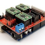
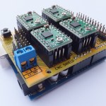
2. We have given back to the GRBL project and developed a ARDUINO CNC SHIELD that is 100% GRBL compatible.(Click here for more details)
This is a quick guide on how to get your GRBL setup and ready to run in Windows.
My current GRBL setup:
- Windows 7 64-bit
- Arduino Duemilanove
- Prototype Shield with headers for 1 Pololu.com stepper drivers.
- Pololu DRV8825 Stepper Drivers
Start by Downloading the following….
- Download the latest stable version of Grbl. (Pre-Build HEX file)
- Download XLoader to upload the HEX file to your Arduino.
- Download the Universal-G-Code-Sender.
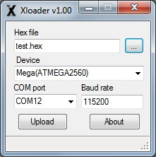
With the Xloader change the settings as follows:
- Select the HEX file you would like to Upload.
- Make sure to select the correct Arduino Board Setup.
- Select the Correct COM Port.
- Keep the Baud Rate as is… (It will change for each board type.
Click on the Upload to send the HEX file to your board.
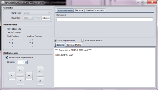
The last step is to install the application that will send commands to your GRBL-Arduino setup.
With the Universal G-Code Sender you will be able to control your GRBL-Arduino board with G-Code commands and it even has arrow buttons to move your stepper motors in place.
Connecting the stepper drivers to your Arduino are covered under the GRBL Pin layout/setup page.
If you are interested in making your own CNC machines we recommend you have a look at the following books:
- Build Your Own CNC Machine – By James Floyd Kelly and P. Hood-Daniel
- CNC Machining Handbook: Building, Programming, and Implementation – By Alan Overby




I have an Arduino Uno, and i’m using the Sparkfun Easydriver boards to control my motors, Which pins on the arduino are used by the gcode sender/grbl software, i got everything set up just dont know which pins are for step and direction. Thank you
Have a look at http://blog.protoneer.co.nz/grbl-arduino-g-code-processor-pin-layout/ . The pins you are interested are D2-D7 (D2-4 are the stepping pins and D5-7 are the direction pins for each axis). Don’t forget about the limit switches as they are life savers.. 😉
Pingback: Arduino CNC Shield – 100% GRBL Compatable | Protoneer.co.nz
Hello, I am using the system proposed by you to control my cnc laser homemade, but the machine is locking up halfway and the program has an error, what can be? I am using windows xp32b, could you help me?
Hi Deives,
Can you tell me more about the error you are receiving and the setup you are running?
thanks.
Hi Bertus, very nice tutorial ! thanks for your help!
here i have 2 that i liked:
https://www.youtube.com/watch?v=107FGoYX1bg
and
http://www.civade.com/post/2011/06/15/piloter-une-CNC-avec-Arduino-GRBL-moteurs-pas-a-pas
..this one is written in french (sorry, i’m beginner AND french…it’s about the hard way to flash grbl)
anyway i followed yours, and then used your update. about hardware i’m driving UNO, with easydriver motor controller from sparkfun and a 42BYGH408AA stepper motor (0.7A usually 12v but i run the test with 5v from my UNO)
so everything might be right, and i feel the motor reacting when i use the command control. but the rotor don’t move outside. i tried with several stepper (even a 5v from old floppy drive), still the same. the stepper motor retailer (chinese…i leave there) told me something about frequency, but i didn’t catch a single word.
have you got any clue? tips, or miracle for me?
anyway thanks a lot, i started my mini cnc project because of you.
Gas.
Hi Gatien,
Thanks for the really nice video on how to use Sketch-up in your CNC workflow.
I think your trouble is with the 5v power source. Easydriver motor controller drivers need more than 5V to work. The input voltage going into the stepper driver and the voltage that the stepper is rated is not the same measurement. Regards.
Hi. At this stage GRBl(g-Code enterpeter) does not support more than 3 axes. To extend the axes number above you 3 you will have to modify the code to allow this. Regards.
Pingback: Workflow | m3ch47r0n1cs
hello..i am having issues with the output.
this is what i have done so far:
1- downloaded hex file from https://github.com/grbl/grbl/downloads
2- using Xloader, i have uploaded the hex file.
3- downloaded grbl controller.
Now when see the outputs from arduino uno pins, except pin 2,3,4 and 5, all pins are consistently high, while these 4 are consistently low.
i need to know where i am making a mistake.
The above mentioned steps are what exactly i have done not even a single thing different.
Please help…
Thanks
As per my previous can you confirm that GRBL is actually functioning? Might be worth sending me an picture of your setup.. info at protoneer dot co dot nz
hola!Bertus!he descargado todo tal cual lo menciona en la guia pero no se como configurar mi grbl. tengo motores de impresora de 12V,pasos 7,5°, no se las velocidades que debo poner (seria 48??) .
Disculpa las molestias!saludos .
Hi Sofia,
My Spanish is not good at all, could you please translate re-ask your question in English?
hi!, How do i configure my GRBL?. I have stepper motor Em 257 and Em 462.I do not know what speed i put. Sorry for my English. regards.
Have a look at http://blog.protoneer.co.nz/configuring-grbl-arduino-based-cnc-controller/
Calibrating the machine takes time and its a set and test process. 😉
Hello!
I have Arduino UNO & cnc sheildv 3.0 with 4 axis
I building cnc foam cutter, how to choose the firmware to 4 axes compatible with GRBL?
At this stage GRBl only supports 3 axes. But its planned to add more. The other option is to write your own software that implements the 4th axis.
I’m very new to this CNC stuff and would like your help.
I’m using your V3 shield and I’m starting to wire everything up and all of that looks straight forward but is there a way to use a probe with your shield??? If so how do I do it as I don’t see a pin for it.
Thanks
Rodney
Hi Rodney, The V3 does not have the Probe specially exposed.(The next board to be released soon will have it) But if you look at the top right of the shield there is a 4x2pin header and one of them is labeled as SCL. That is the A5/Probe pin on the UNO.
Hi Bertus, I´m using UNO, grbl 0.9i and your board V3.
Is there an updated pin map? I keep getting a ‘probe triggered’ error.
Thanks!
Hi. GRBL 0.9i has a small change in pin configuration(PWM spindle). Z-limit and Spindle enable pins swapped. But that should not affect the A5 probe pin. Are you using the the A5 pin or the SCL pin? What is your Probe setting($6)? If you are not using Probe you can set $6=1 and add a stronger Pull-up resistor to get rid of any noise.
Hi Bertus. Here’s what I have and what;s going on. Windows Vista 32 bit, GRBL 0.9, Ver 3 CNC shield, clone “A” to “Y” axis, set VREF for .8a, 3.75 degree steppers on A4988 drivers per Pololou directions. What happens is the “A” & “Y” do not turn the same. They shudder and one may turn 3/4 turn, and then the other. “X” & “Z” will shudder and whine also. I’ve even reset GRBL for 96 steps per mm from the default, swapped motors, swapped drivers, still they shudder and whine and don’t turn the same. It was no different with GRBL 8. Any thoughts or ideas where I need to go next? If they turn for an extended period, they all run smooth but just on start and stop.
Hi Bertus.
It looks like it was a bad driver.
Sorry for the late reply, but I am happy that you managed to get ti going. 😉
joystick feature in the future please
Pingback: CNC 1 | Teachables